Eureka AIR delivers breakthrough ideas for toughest innovation challenges, trusted by R&D personnel around the world.

Power assisted steering for an automobile

a technology of power assisted steering and automobiles, which is applied in the direction of steering components, power driven steering, position/direction control, etc., can solve the problems of complicated calibration of the torque sensor used in such a power assisted steering system, and affecting the safety of the driver and passengers

Active Publication Date: 2011-07-28
BERLIN PACKAGING +1
View PDF9 Cites 5 Cited by
  • Summary
  • Abstract
  • Description
  • Claims
  • Application Information

AI Technical Summary

Benefits of technology

[0009]The present invention primarily aims to provide a power assisted steering system without torque sensor that makes it possible to keep the feeling of a driver of a vehicle equipped with this system consistent with the dynamics of the vehicle.
[0021]The determination of the control signal of the electric assist motor in particular from the first and second operation signals defined above makes it possible to control the assist effort provided by the electric assist motor so as to make the driver's feeling tend towards a feeling normally desired for a given dynamic situation, without requiring the presence of a dedicated torque sensor.
[0022]Thus, the power assisted steering system according to the invention makes it possible to keep the feeling of a driver of an automobile equipped with this system consistent with the dynamics of the automobile, and therefore not to compromise the safety of the automobile's driver and passengers.

Problems solved by technology

It must be noted that the torque sensor used in such a power assisted steering system is complex to implement and calibrate.
However, such a power assisted steering system is likely to cause instabilities in the control of the assist motor that can compromise the safety of the driver and passengers in an automobile equipped with such a power assisted steering system.
Indeed, under limit usage conditions (e.g. under conditions with very low traction, very sudden changes of traction of the black ice patch type), the automobile's driver's feeling, i.e. the torque the driver must exert on the steering wheel to move it, can be inconsistent with the driving situation and therefore bother the driver.
This disruption can cause undesired movements of the steering wheel, and thereby compromise the safety of the driver and any passengers in the automobile.

Method used


Image

  • Power assisted steering for an automobile
  • Power assisted steering for an automobile
  • Power assisted steering for an automobile

Examples


Embodiment Construction

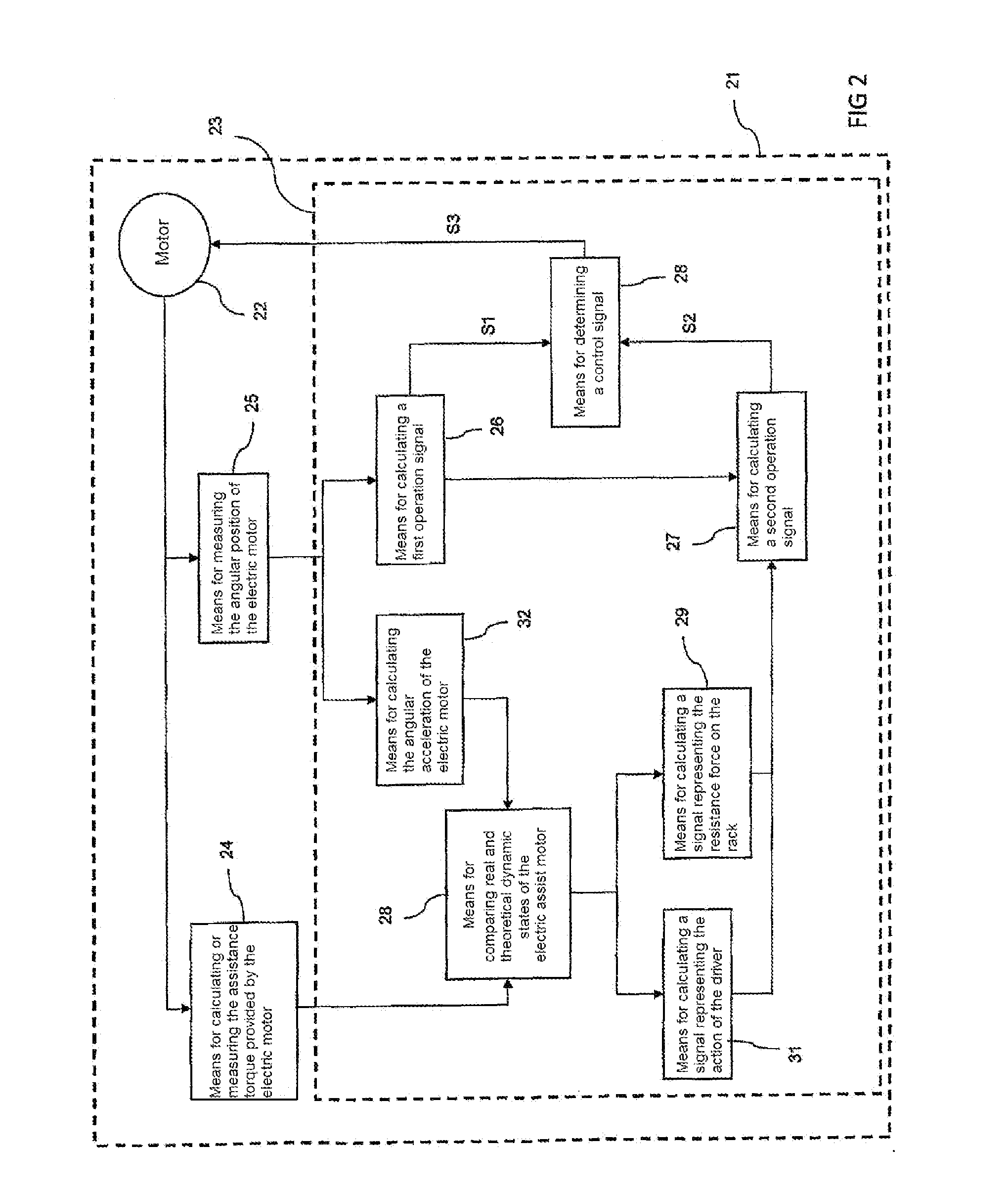
[0035]FIG. 2 shows an electric power assisted steering system 21 for an automobile comprising:[0036]an electric assist motor 22 arranged to assist the manual force exerted by a driver on the steering wheel of the automobile,[0037]a processing unit 23 arranged to control the electric assist motor,[0038]a means 24 for calculating or measuring the assistance torque output by the electric assist motor,[0039]a means 25 for measuring the angular position of the electric assist motor.

[0040]The processing unit 23 comprises:[0041]a means 26 for calculating a first operation signal 51 arranged to calculate the first operation signal as a function of the angular position of the electric assist motor,[0042]a means 27 for calculating a second operation signal S2 arranged to calculate the second operation signal,[0043]a means 28 for determining a control signal S3 of the assist motor as a function of the first operation signal 51 and the second operation signal S2.

[0044]The processing unit 23 als...


PUM


Abstract

The invention relates to a power assisted steering system (21) that includes an electric assist motor (22) arranged to assist the manual force exerted by a driver on the steering wheel of the automobile, a processing means (23) arranged to control the electric assist motor (22), the processing means (23) including a means (28) for predetermining a signal (S3) for controlling the electric assist motor on the basis of a first operation signal (S1) determined on the basis of the angular position of the electric assist motor, and a second operation signal (S2) determined on the basis of the measurement or calculation of the angular acceleration of the electric assist motor and the measurement or calculation of the assistance torque output by the electric assist motor.

Description

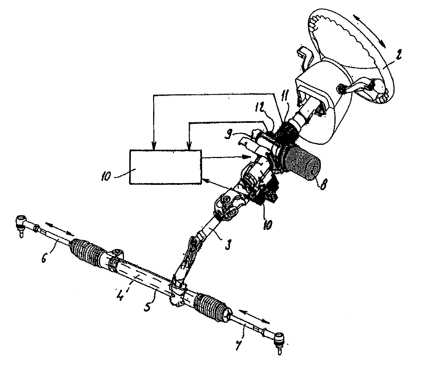
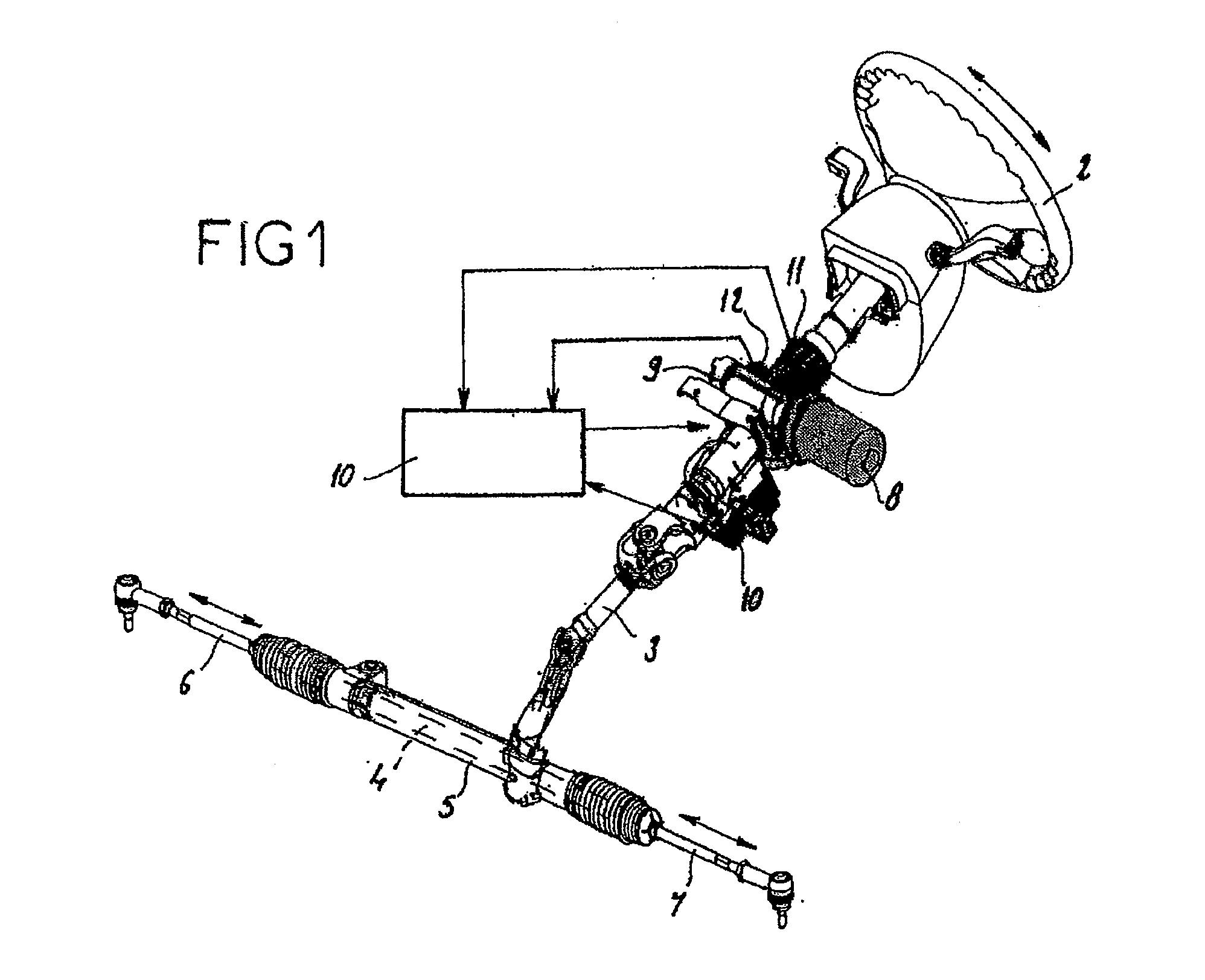
TECHNICAL FIELD[0001]The present invention relates to a power assisted steering system, for example electric, for an automobile.BACKGROUND[0002]FIG. 1 recalls the main elements making up a power assisted steering system, for example electric, of an automobile. Such a steering system comprises, on one hand, a mechanical portion comprising a steering wheel 2 rotatably connected to a steering column 3, whereof the remote end of the wheel 2 carries a steering pinion engaged with a steering rack 4, slidingly mounted in a steering gear-box 5. The two opposite ends of the steering rack 4 are connected, respectively, via connecting rods 6 and 7, to the right and left steering wheels (not shown) of the vehicle. The steering system comprises, to assist the manual force exerted by the vehicle's driver on the wheel 2, an electric assist motor 8 with two directions of rotation. The output shaft of the assist motor is coupled, via a speed reducer 9, in particular with worm and cylindrical worm wh...

Claims


Application Information

Patent Timeline
Patent Type & Authority Applications(United States)
IPC IPC(8): B62D6/00B62D5/04
CPCB62D5/0463B62D6/008B62D7/159B62D6/02B62D6/04B62D5/0481
Inventor PILAZ, PIERRECASSAR, STEPHANEMOULAIRE, PASCAL
Owner BERLIN PACKAGING
Why Eureka
Eureka Blog
Learn More