
SINGLE DIELECTRIC BARRIER DISCHARGE PLASMA ACTUATORS WITH IN-PLASMA catalysts AND METHOD OF FABRICATING THE SAME

a technology of dielectric barrier and plasma actuator, which is applied in the direction of physical/chemical process catalyst, metal/metal-oxide/metal-hydroxide catalyst, paper/cardboard container, etc., can solve the problem of greater collisions per unit time between ions and neutral background gas

Inactive Publication Date: 2011-07-28
FINE NEAL E +1
View PDF9 Cites 36 Cited by
  • Summary
  • Abstract
  • Description
  • Claims
  • Application Information

AI Technical Summary

Benefits of technology

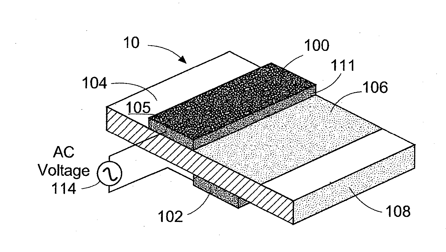
[0008]It has been discovered that the force exerted on the background gas by a single dielectric barrier discharge plasma actuator is enhanced by the addition of a catalyst within the plasma volume. The present invention provides a catalyst-enhanced single dielectric barrier discharge plasma actuator consisting of a pair of offset electrodes separated by a layer of solid dielectric material, the exposed surface of which is coated or impregnated with a thin layer of catalytic material.
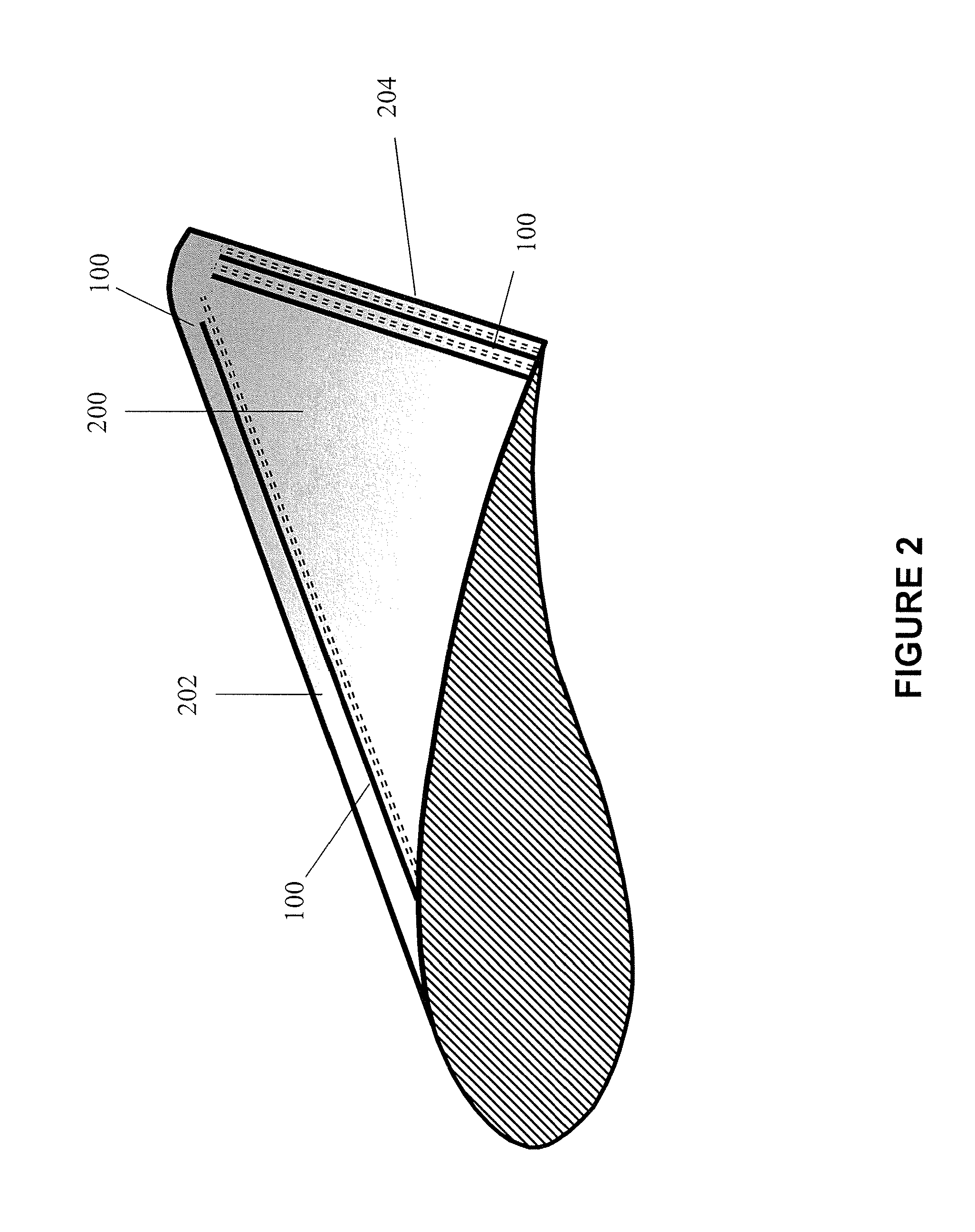
[0010]Research indicates that the rate at which certain reactive species produced in the plasma, including, for example, the superoxide anion O2−, is enhanced through catalytic activity within the plasma and on the surface of the dielectric [16]. When the catalysts are fixed to the surface of—or embedded throughout—the dielectric material in a single dielectric barrier discharge plasma actuator, a greater density of ions is produced in the plasma, leading to a greater number of collisions per unit time between the ions and the neutral background gas. This results in enhanced momentum transfer to the background gas. Hence, single dielectric barrier discharge plasma actuators with a thin coating of catalytic material fixed to the exposed surface of the dielectric, or embedded throughout the dielectric, will lead to enhanced control and improvement of the airflow over lifting and non-lifting bodies.

Problems solved by technology

When the catalysts are fixed to the surface of—or embedded throughout—the dielectric material in a single dielectric barrier discharge plasma actuator, a greater density of ions is produced in the plasma, leading to a greater number of collisions per unit time between the ions and the neutral background gas.

Method used


Image

  • SINGLE DIELECTRIC BARRIER DISCHARGE PLASMA ACTUATORS WITH IN-PLASMA catalysts AND METHOD OF FABRICATING THE SAME
  • SINGLE DIELECTRIC BARRIER DISCHARGE PLASMA ACTUATORS WITH IN-PLASMA catalysts AND METHOD OF FABRICATING THE SAME
  • SINGLE DIELECTRIC BARRIER DISCHARGE PLASMA ACTUATORS WITH IN-PLASMA catalysts AND METHOD OF FABRICATING THE SAME

Examples


Embodiment Construction

[0022]Persons of ordinary skill in the art will realize that the following disclosure is illustrative only and not in any way limiting. Other embodiments of the invention will readily suggest themselves to such skilled persons having the benefit of this disclosure.

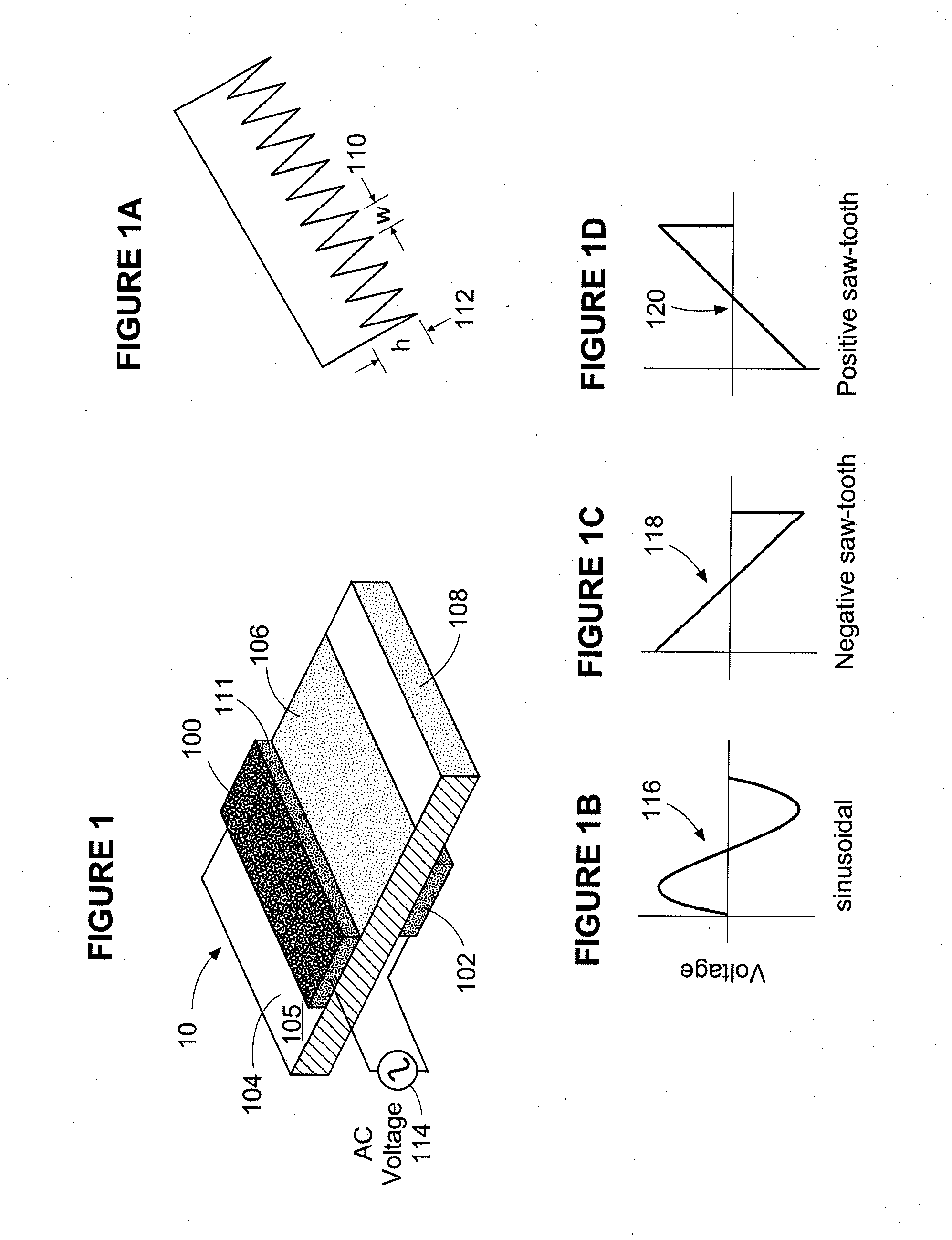
[0023]Referring now to the drawings in detail and initially to FIG. 1, a single dielectric barrier discharge plasma actuator 10 according to one embodiment of the invention includes an exposed electrode 100 and a covered electrode 102 which are offset and separated by a layer of dielectric material 104. An alternating current voltage is passed between the electrodes from a source 114 in any known and convenient manner. When the current source is operating and when the voltage exceeds a minimum value, plasma is formed in the area which is adjacent electrode 100 and above electrode 102.

[0024]As shown in FIG. 1, in accordance with the present invention, a thin layer of catalyst 106 is fixed to the exposed surface of the diele...


PUM

PropertyMeasurementUnit
Pressureaaaaaaaaaa
Electric potential / voltageaaaaaaaaaa

Abstract

A single dielectric barrier plasma actuator is disclosed which includes a pair of offset electrodes and a dielectric barrier therebetween which includes a catalyst at least in the area adjacent one of the electrodes for enhancing the force created in the background gas by the actuator.

Description

[0001]This application claims the benefit of U.S. Provisional Application No. 61 / 299,175 filed Jan. 28, 2010.BACKGROUND OF THE INVENTION[0002]1. Field of the Invention[0003]The present invention relates to a catalyst-enhanced single dielectric barrier discharge plasma actuator for use in active control of lift and drag forces generated by wings, airfoils, rotating turbine blades, helicopter blades, bluff bodies, and other lifting and non-lifting bodies operating in an air stream.[0004]2. Description of the Related Art[0005]Single dielectric barrier discharge plasma actuators, also referred to as paraelectric gas flow accelerators and as plasma actuators, have been used to manipulate airflows on a variety of lifting and non-lifting bodies. These actuators, which typically consist of a pair of offset electrodes separated by a dielectric material, generate a force on the neutral background gas that results in a paraelectric gas flow. Applications for such actuators include, for example...

Claims


Application Information

Patent Timeline
IPC IPC(8): H05H1/24B32B37/02B32B37/14F15D1/00B01J37/02B01J37/34B01J37/12B01J37/04B01J37/08
CPCB01J21/063B01J23/06Y10T156/10B01J35/004H05H1/24B01J23/30Y10T137/0318H05H1/2439B01J35/39
Inventor FINE, NEAL E.BRICKNER, STEVEN J.
Owner FINE NEAL E
Learn More