
Real-Time Geometry Aware Projection and Fast Re-Calibration

a real-time geometry and projection technology, applied in the field of projector camera systems, can solve the problems of inability to summarize all of the prior attempts, inability to continuously correct the imagery being projected, and inability to continuously adjust the estimation algorithm in real time,

Inactive Publication Date: 2011-07-21
SEIKO EPSON CORP
View PDF10 Cites 59 Cited by
  • Summary
  • Abstract
  • Description
  • Claims
  • Application Information

AI Technical Summary

Benefits of technology

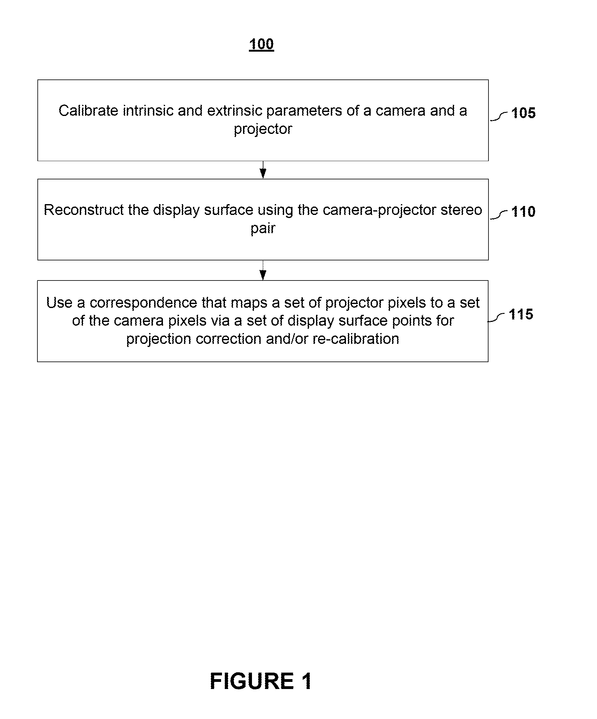
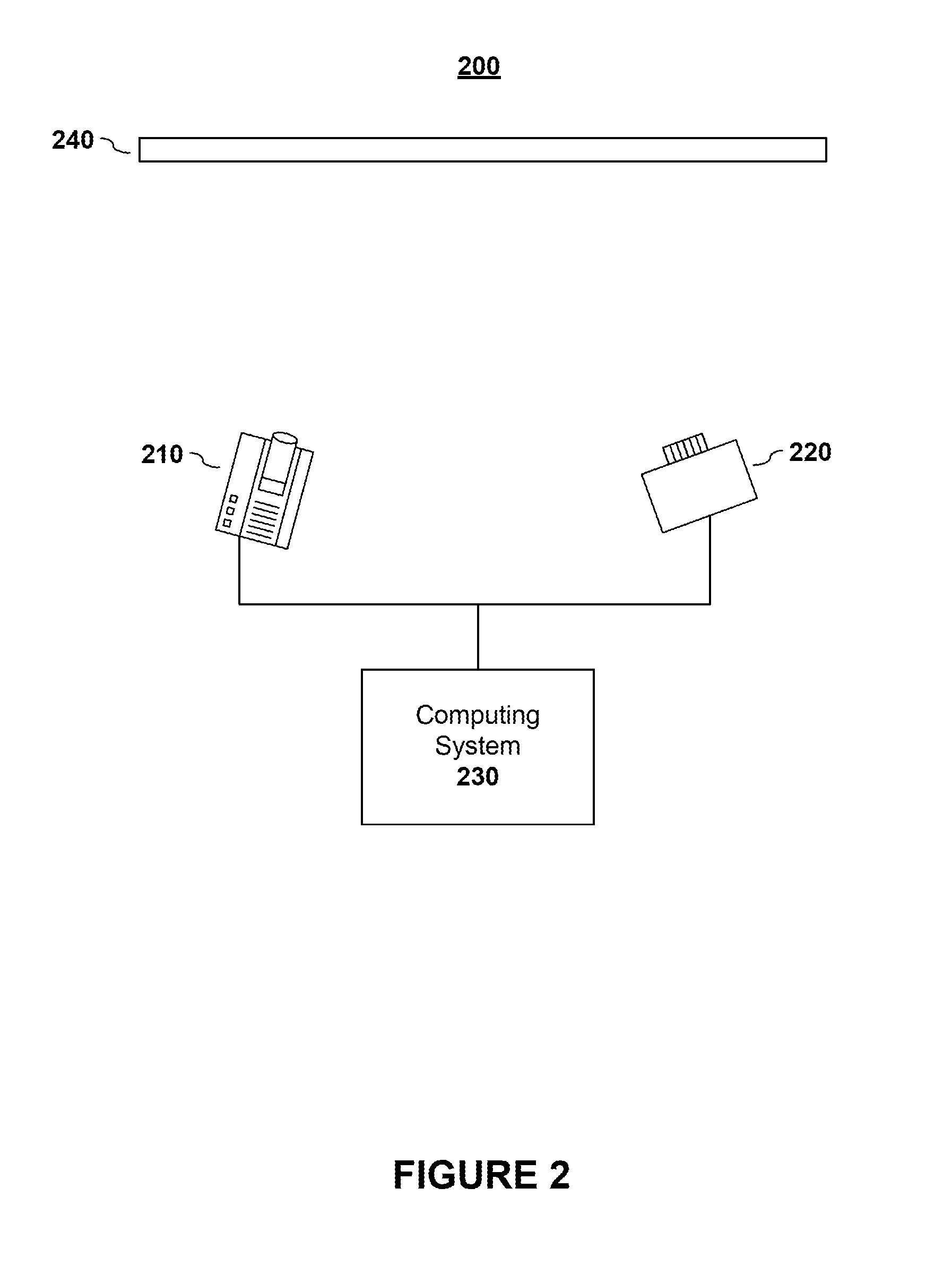
[0012]To alleviate the aforementioned limitations, presented herein are systems and methods employing, in embodiments, a single camera and a single projector with an arbitrary displaying surface. In embodiments, systems and methods are able to recalibrate automatically the projector with arbitrary intrinsics and pose, as well as render for arbitrarily desired viewing point. In contrast to previous methods, the methods disclosed herein use the observing camera and the projector to form a stereo pair. In embodiments, structured light is used to perform pixel level fine reconstruction of the display surface.

Problems solved by technology

Accordingly, it would be impossible to summarize all of the prior attempts.
One issues with this approach, however, it that the estimation algorithm works in an iterative manner and is not suitable for continuous correction in real time.
However, one major drawback of such an approach is that it requires a portion of the projector's dynamic range to be sacrificed, which will, in turn, cause a degradation of the imagery being projected.
While these methods offer some advantages over prior display options, the system calibration is often a tedious undertaking.

Method used


Image

  • Real-Time Geometry Aware Projection and Fast Re-Calibration
  • Real-Time Geometry Aware Projection and Fast Re-Calibration
  • Real-Time Geometry Aware Projection and Fast Re-Calibration

Examples


Embodiment Construction

[0029]In the following description, for purpose of explanation, specific details are set forth in order to provide an understanding of the invention. It will be apparent, however, to one skilled in the art that the invention may be practiced without these details. One skilled in the art will recognize that embodiments of the present invention, some of which are described below, may be incorporated into a number of different systems and devices, including by way of illustration and not limitation, multimedia systems, theater systems, video conference systems, projection systems, gaming systems, computer systems, and the like. Aspects of the present invention may be implemented in software, hardware, firmware, or combinations thereof.

[0030]Components, or modules, shown in block diagrams are illustrative of exemplary embodiments of the invention and are meant to avoid obscuring the invention. It shall also be understood that throughout this discussion that components may be described a...


PUM


Abstract

Aspects of the present invention include systems and methods for recalibrating projector-camera systems. In embodiments, systems and methods are able to recalibrate automatically the projector with arbitrary intrinsic and pose, as well as render for arbitrarily desired viewing point. In contrast to previous methods, the methods disclosed herein use the observing camera and the projector to form a stereo pair. Structured light is used to perform pixel-level fine reconstruction of the display surface. In embodiments, the geometric warping is implemented as a direct texture mapping problem. As a result, re-calibration of the projector movement is performed by simply computing the new projection matrix and setting it as a camera matrix. For re-calibrating the new view point, the texture mapping is modified according to the new camera matrix.

Description

BACKGROUND[0001]A. Technical Field[0002]The present invention pertains generally to projector-camera systems, and relates more particularly to adaptive projector display systems.[0003]B. Background of the Invention[0004]The increasing prevalence of multimedia systems, such as computer systems, gaming system, videoconference systems, projector systems, and home theater systems, has resulted in projector display systems operating within a wide variety of conditions. Adaptive projector display systems have been developed to address projection under various conditions. For example, research into adaptive projector display systems have attempted to find ways to correct for color distortions, display surface distortions, and other calibration issues. The research in this area has resulted in methods that improve the robustness of the projector systems.[0005]As these systems are increasing being used by average consumers who are unfamiliar with projection technology and calibration techniq...

Claims


Application Information

Patent Timeline
IPC IPC(8): H04N17/00G03B17/54
CPCG06T7/0018H04N9/3182G06T2207/20041H04N9/3194H04N9/3185G06T7/80
Inventor DING, YUANYUANXIAO, JING
Owner SEIKO EPSON CORP
Learn More