
Valve-controlled positive displacement machine

a positive displacement machine and valve control technology, applied in the direction of piston pumps, servomotor components, servomotors, etc., can solve the problems of limited cross-sectional area, limited maximum possible pressure fluid volume flow for the pressure equilibrium, and inability to control the valve-controlled positive displacement machine, etc., to achieve the effect of increasing volume flow and reducing circuitry costs

Inactive Publication Date: 2011-07-21
ROBERT BOSCH GMBH
View PDF13 Cites 0 Cited by
  • Summary
  • Abstract
  • Description
  • Claims
  • Application Information

AI Technical Summary

Benefits of technology

[0011]By comparison, it is the object of the invention to create a valve-controlled positive displacement machine which with reduced circuitry expense in terms of apparatus makes increased volume flows through the high-pressure valve possible.
[0013]The valve-controlled hydrostatic positive displacement machine (DDU) according to the invention has a plurality of cylinder-piston units which are each activatable or deactivatable, via at least one low-pressure valve and via one high-pressure valve, for adjusting a volume flow of the positive displacement machine. A valve body of the high-pressure valve is embodied according to the invention as a valve slide, and operative faces acted upon in or counter to a displacement direction are essentially pressure-balanced. Thus a high-pressure valve for a DDU is created which can be switched with less switching force and thus with less apparatus expense, without requiring prior pressure relief of the valve body. Comparatively large volume flows through the high-pressure valve are then possible, with a comparatively smaller switching force.
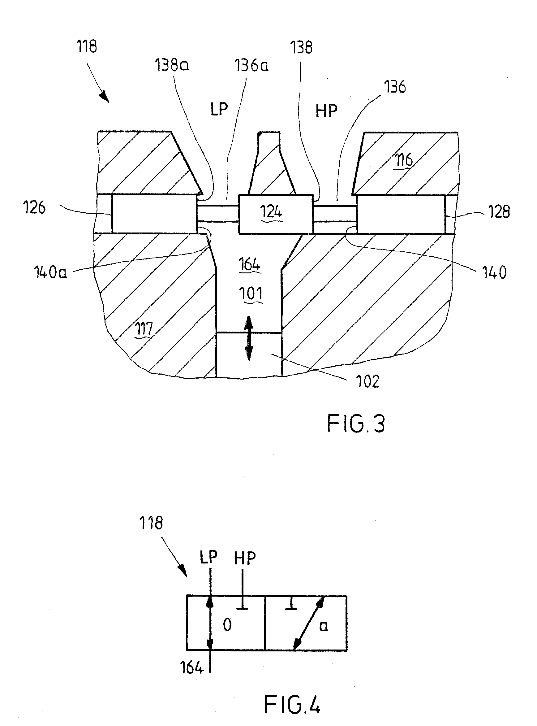
[0018]In an especially preferred exemplary embodiment, the valve slide controls the low-pressure valve as well. The high-pressure valve and the low-pressure valve are disposed in a common 3 / 2-way valve housing, which has a high-pressure port, a low-pressure port, and a port to the cylinder. Thus the construction of the high-pressure valve and of the low-pressure valve per cylinder of the positive displacement machine of the invention is simplified.

Problems solved by technology

In such hydrostatic positive displacement machines, it is disadvantageous that all the cylinder-piston units are always active.
A disadvantage of such valve-controlled positive displacement machines is the cross-sectional area, which is restricted by the magnetic force of the pilot control needle.
With increasing pump rpm, both the cross-sectional area made available by the pilot control needle and the maximum possible pressure fluid volume flow for the pressure equilibrium are therefore limited.

Method used


Image

  • Valve-controlled positive displacement machine
  • Valve-controlled positive displacement machine
  • Valve-controlled positive displacement machine

Examples


Embodiment Construction

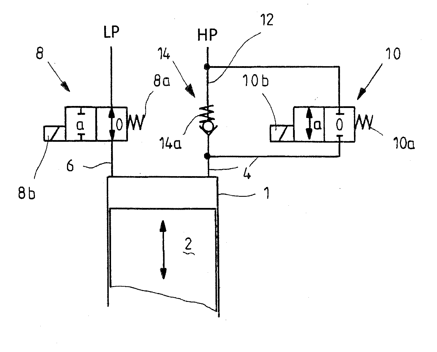
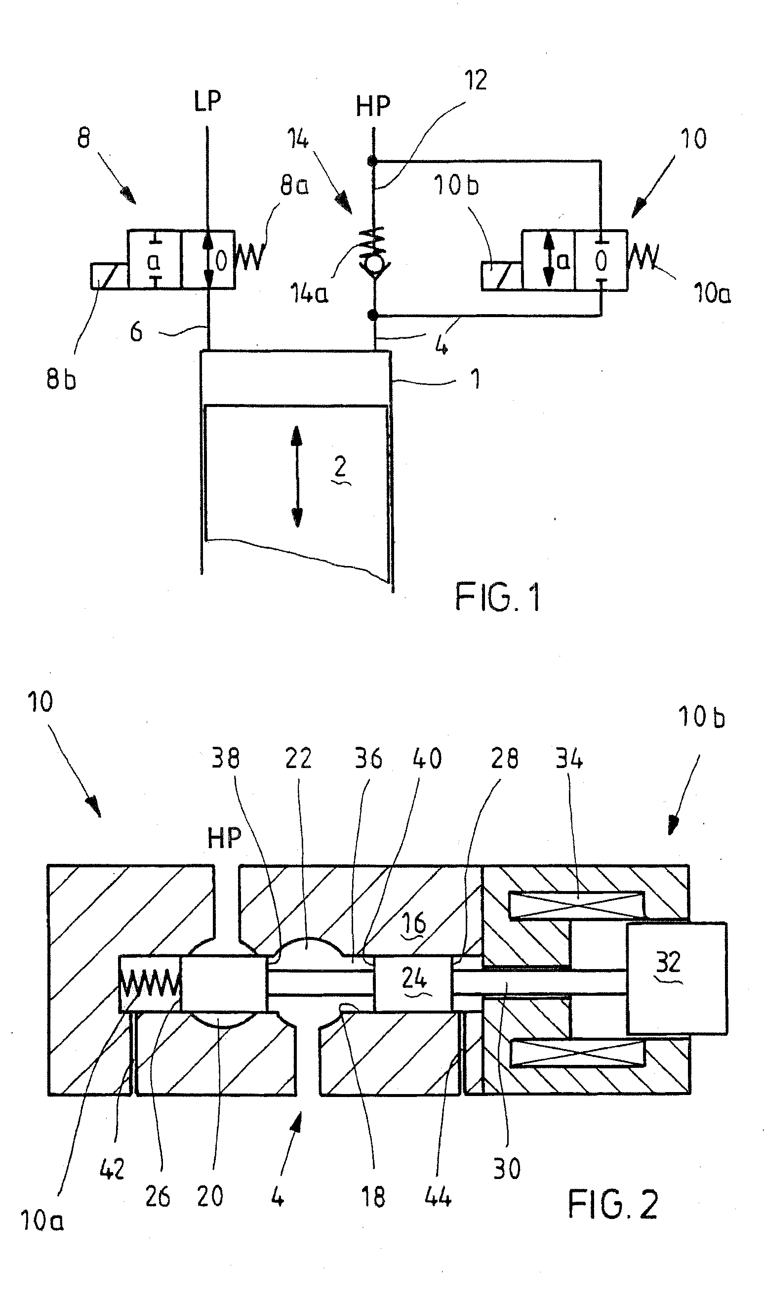
[0033]FIG. 1 shows a circuit diagram of a cylinder-piston unit of a positive displacement machine according to the invention that has a plurality of such units, each having a cylinder 1, and a piston 2. Each cylinder 1 communicates with a high-pressure port HP of the positive displacement machine of the invention via a high-pressure line 4 and with a low-pressure port LP via a low-pressure line 6.

[0034]The communication with the low-pressure port LP is controlled via a low-pressure valve 8, and the communication with the high-pressure port HP is controlled via a high-pressure valve 10. The low-pressure valve 8, in a basic position 0 prestressed by a spring 8a, enables the communication with the cylinder 1, while in a switching position a switched by an actuator 8b, it blocks the cylinder 1. The high-pressure valve 10, in a basic position 0 prestressed by a spring 10a, blocks the cylinder 1, while in a switching position a switched by an actuator 10b, it enables the communication wit...


PUM


Abstract

A valve-controlled hydrostatic positive displacement machine (DDU) is proposed, with a plurality of cylinder-piston units which are each activatable or deactivatable, via at least one low-pressure valve and via one high-pressure valve, for adjusting a volume flow of the positive displacement machine. According to the invention a valve body of the high-pressure valve is embodied as a valve slide, and operative faces acted upon in or counter to a displacement direction are essentially pressure-balanced.

Description

CROSS-REFERENCE TO RELATED APPLICATION[0001]This application is based on German Patent Application 10 2010 004 808.9 filed on Jan. 18, 2010.BACKGROUND OF THE INVENTION[0002]1. Field of the Invention[0003]The invention relates to a valve-controlled positive displacement machine.[0004]2. Description of the Prior Art[0005]In conventional positive displacement machines, which can be embodied for instance as radial piston or axial piston engines, the control of the inflow and outflow, or of the connections with the high and low pressure of the individual cylinder-piston units, is effected mechanically. In the case of an axial piston pump, for instance, two pressure pockets are used, by way of which the communications with the high-pressure side and the low-pressure side open during a certain range of the circular path and thus during a certain portion of the stroke of the cylinder-piston units. In radial piston pumps, one mechanical high-pressure valve and one mechanical low-pressure val...

Claims


Application Information

Patent Timeline
Patent Type & Authority Applications(United States)
IPC IPC(8): F15B13/04
CPCF04B7/0015F04B7/0076F04B7/0053
Inventor MISCHKER, KARSTENWEINGART, JOERGWALTER, RAINERSCHWADERER, PETER
Owner ROBERT BOSCH GMBH
Learn More