Threaded fastener and related method of installation

a technology of threaded fasteners and screws, applied in the field of fasteners, can solve the problems of joists into which the side angled screws are prone to stripping, the “side angled screws” are relatively unnoticeable by an observer looking straight down at the boards, and the tendency of torx screw drive features to be prone to stripping, etc., to achieve the effect of convenient and consistent us

Active Publication Date: 2011-07-14
NAT NAIL
View PDF82 Cites 11 Cited by
  • Summary
  • Abstract
  • Description
  • Claims
  • Application Information

AI Technical Summary

Benefits of technology

[0009]A self-threading fastener in the form of a screw including a head is provided. This fastener can be in the form of a screw that can be easily and consistently used in screwing operations where the fastener penetrates a surface of a work piece, such as a board or other building material, and optionally fastens the work piece or material to another work piece, article or underlying support structure.
[0012]In still another embodiment, the conical end portion can define a v-shape flute to improve the initial advancement of the screw into the work piece, and to initially remove material from the work piece adjacent the sharp point, thereby allowing the sharp point to quickly advance into the work piece.
[0014]The screw described herein provides a simple and efficient structure that is easily drilled into a work piece at an angle to hold the work piece in a position relative to an underlying support structure. With the drive feature, the screw can be advanced and rotated under significant torque without the drive feature being stripped or significantly damaged by an associated drive tool. This can prevent unwanted screw failure and other issues associated with continuing to advance or removing a stripped out screw.

Problems solved by technology

When boards are placed side-by-side one another, these “side angled screws” are relatively unnoticeable by an observer looking straight down at the boards.
Because the screw heads of side angled screws are outfitted with such a relatively small T-10 screw drive, only a relatively low amount of torque can be applied to the screws before the TORX screw drive feature is prone to stripping.
This can be particularly problematic where the boards or joists into which the side angled screws are drilled are particularly dense, either from being cold or being constructed from a wood or composite that is dense.
It also can be problematic where a user improperly sets their installation tool to a high torque, and ends up stripping out the head.
It can further pose issues where the screws are constructed from inferior metals or by using manufacturing techniques that lack quality control.

Method used


Image

  • Threaded fastener and related method of installation
  • Threaded fastener and related method of installation
  • Threaded fastener and related method of installation

Examples


Embodiment Construction

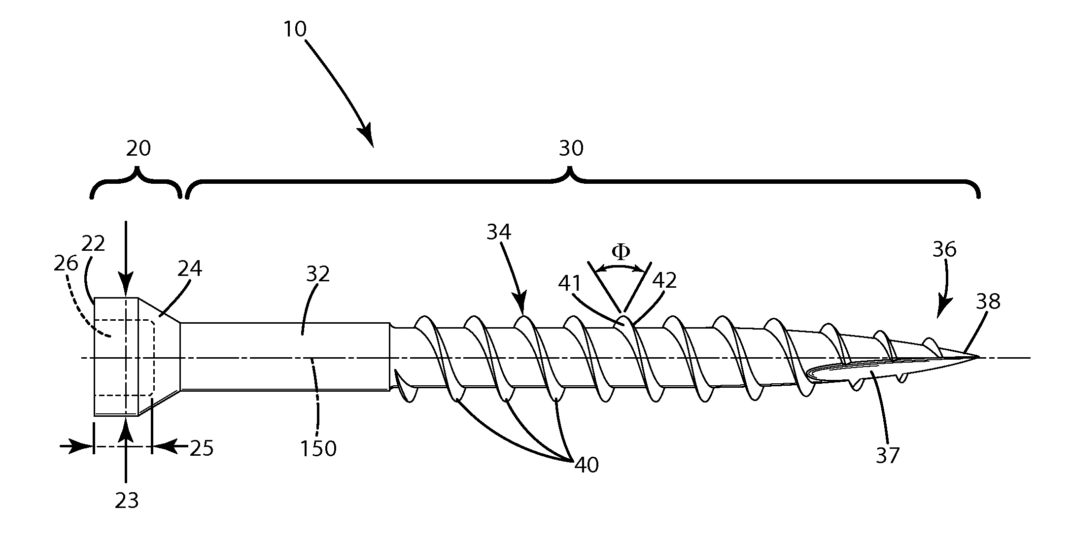
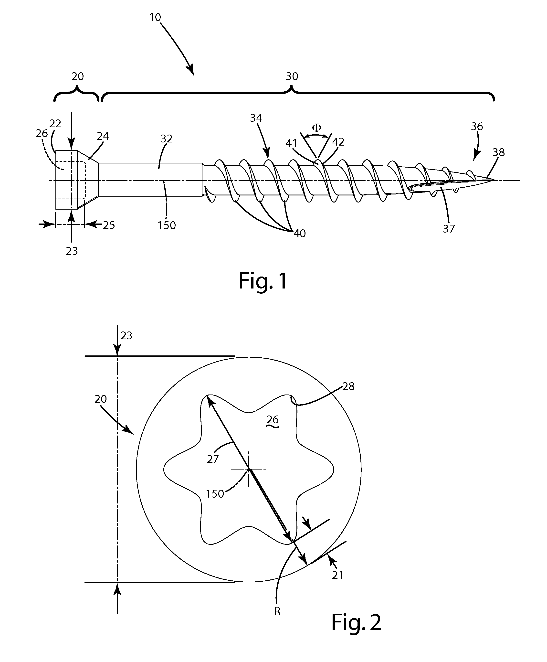
[0021]A self-threading screw of the current embodiment is illustrated in FIGS. 1-3 and generally designated 10. The fastener can be in the form of a threaded fastener, and more particularly, a screw 10 including a head 20 and a shaft 30. The head can include an upper portion 22 and a lower portion 24. The upper portion 22 is of a uniform diameter 23 (FIG. 2), which can range from about 0.197 to 0.202 inches in diameter, or can be of other dimensions if desired. The upper portion 22 of the head can include an exterior surface that is substantially cylindrical and of the uniform diameter 23 from the end of the head where the opening to the drive feature is located, to where the upper portion 22 begins to transition to the lower portion 24, where it tapers down to the shaft 30 of the screw 10. Optionally, the lower portion 24 can be in the form of a frustoconical portion.

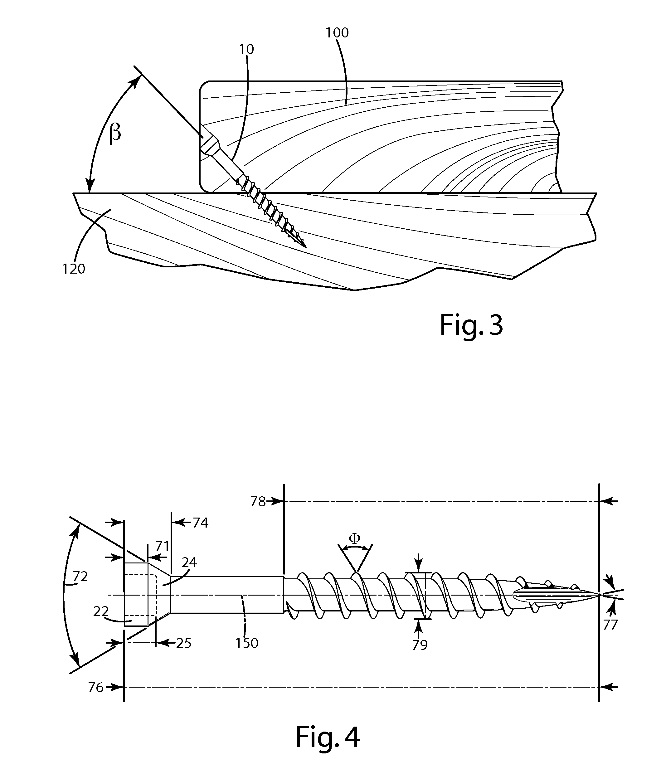
[0022]As shown in FIG. 4, the upper portion 22 can be of a length dimension 71 that is optionally about 0.01 to abou...


PUM

PropertyMeasurementUnit
thicknessaaaaaaaaaa
thread angleaaaaaaaaaa

Abstract

A fastener including a head defining a hexalobular drive hole, a shaft, threads and a pointed end. The hexalobular drive hole can include points having an outermost portion, and the head can include an outer surface, where a thickness of about 0.01 inches to about 0.04 inches is defined between the outer surface and each respective point. The outer surface can be cylindrical, and can transition to a tapered portion that is joined with the shaft. The tapered portion can be frustoconical, angled and / or curvilinear. A related method of installation is provided for advancing the fastener into the side of a first board at an angle to fasten the first board to an underlying second board.

Description

BACKGROUND OF THE INVENTION[0001]The present invention relates to a fastener, and more particularly to a screw including a screw head and a related method of installation.[0002]There are a variety of commercially available fasteners that are designed to fasten a work piece, such as a wooden board or a composite element, to a substrate, such as a subfloor, joist or other underlying support structure. In many cases, these fasteners are in the form of threaded screws including: a large, bugle-shaped head to which an installation drive attaches (for example, a Phillips or star drive screw head); a shaft that projects from the head; threads on the shaft, and a sharpened point, which centers the screw on a location, and initially pierces the board so that the screw can advance into it. These types of screws are typically drilled downward, in an orthogonal manner, into the top of a board to fasten the board to an underlying support, such as a joist. Most of the holding power of such screws...

Claims


Application Information

Patent Timeline
Patent Type & Authority Applications(United States)
IPC IPC(8): F16B35/04B23P11/00
CPCF16B25/0015Y10T29/49947F16B25/103F16B25/0084
Inventor VANDENBERG, ROGER A.
Owner NAT NAIL
Why Eureka
Try Eureka