Fastener, installation tool and related method of use

a technology of installation tools and fasteners, which is applied in the direction of fastening means, screwdrivers, wrenches, etc., can solve the problems of splintering of the lower corner of the board from the rest of the board, cutting or drilling into the wood, and the “side angled screws” are relatively unnoticed by an observer looking straight down at the boards, so as to achieve convenient and consistent use

Active Publication Date: 2015-09-01
NAT NAIL
View PDF224 Cites 13 Cited by
  • Summary
  • Abstract
  • Description
  • Claims
  • Application Information

AI Technical Summary

Benefits of technology

[0011]In one embodiment, a fastener including an end that pre-bores a hole for the remainder of the screw is provided. This fastener can be in the form of a screw that can be easily and consistently used in screwing operations where the fastener penetrates a surface of a work piece, such as a board or other building material, and optionally fastens the work piece or material to another work piece, article or underlying support structure.

Problems solved by technology

While the acutely angled surfaces of such a screw can pre-drill a hole for the screw, the acutely angled surfaces also rapidly cut or drill into the wood.
When boards are placed side-by-side one another, these “side angled screws” are relatively unnoticeable by an observer looking straight down at the boards.
An issue with conventional side angled screws concerns their configuration and the manner in which they advance into a work piece.
The drawing of the shaft between the grains or fibers frequently causes the lower corner of the board to splinter from the remainder of the board (if wooden) or to bulge out the lower corner of the board (if composite) due to the wedging action of the shaft and threads in the corner.
Thus, conventional side angled screws can tend to damage the corner of the board into which they are advanced, particularly if they are imprecisely positioned or angled, or advanced too quickly into the board, or if the board is weak or dense.
Typically, this will reduce the holding strength of the screw, which of course, is undesirable.
For example, because the bore guide is distanced from the side of the board, screws advanced through the bore sometimes are placed improperly relative to the lower corner of the board.
Further, if the tool is not perfectly aligned, the pointed tip of the screw sometimes can grab and pull the screw into the board at an undesirable angle, which can cause the screw to bind against the bore of the jig body and slow its advancement, or cause additional wear and tear on the guide.
In addition, while the pins of the aforementioned tool can help locate the bore guide, those pins can also be a detriment.
Accordingly, the tool might not fit properly over some overly wide, “outlier” boards in a particular project.
Alternatively, where certain boards are overly narrow, the tool may improperly align the bore guide too far from the side of the board, so that the screw misses the board or splinters off its lower corner.
Further, the tools mentioned above typically are used for applications where the boards are spaced a distance from one another so that upon installation, there is a noticeable gap or space between immediately adjacent, installed boards.
Where the boards are prone to shrinkage, for example, by the boards drying over time, use of the above tool to install such boards can create unsightly or excessively wide gaps in the structure.

Method used


Image

  • Fastener, installation tool and related method of use
  • Fastener, installation tool and related method of use
  • Fastener, installation tool and related method of use

Examples


Embodiment Construction

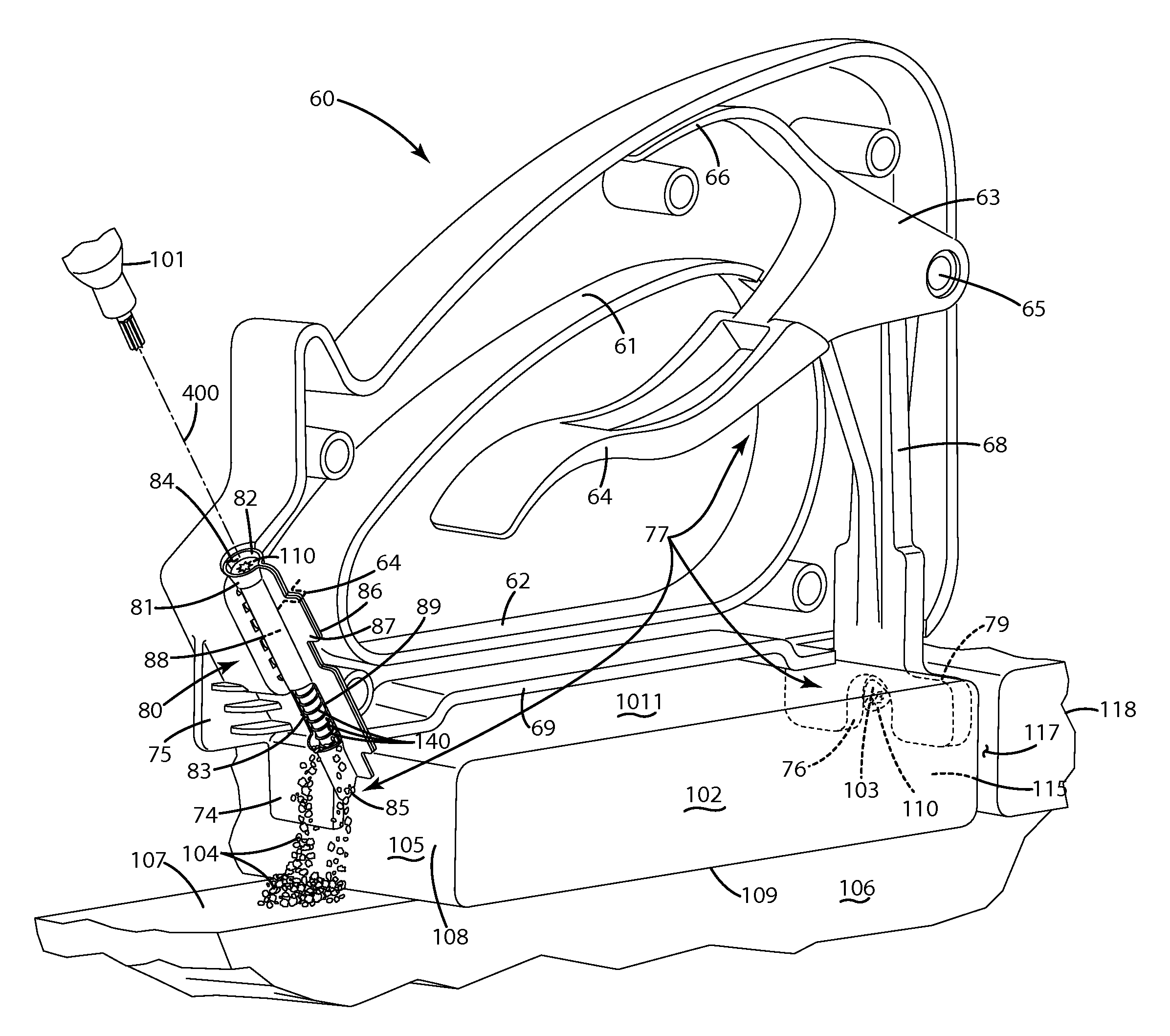
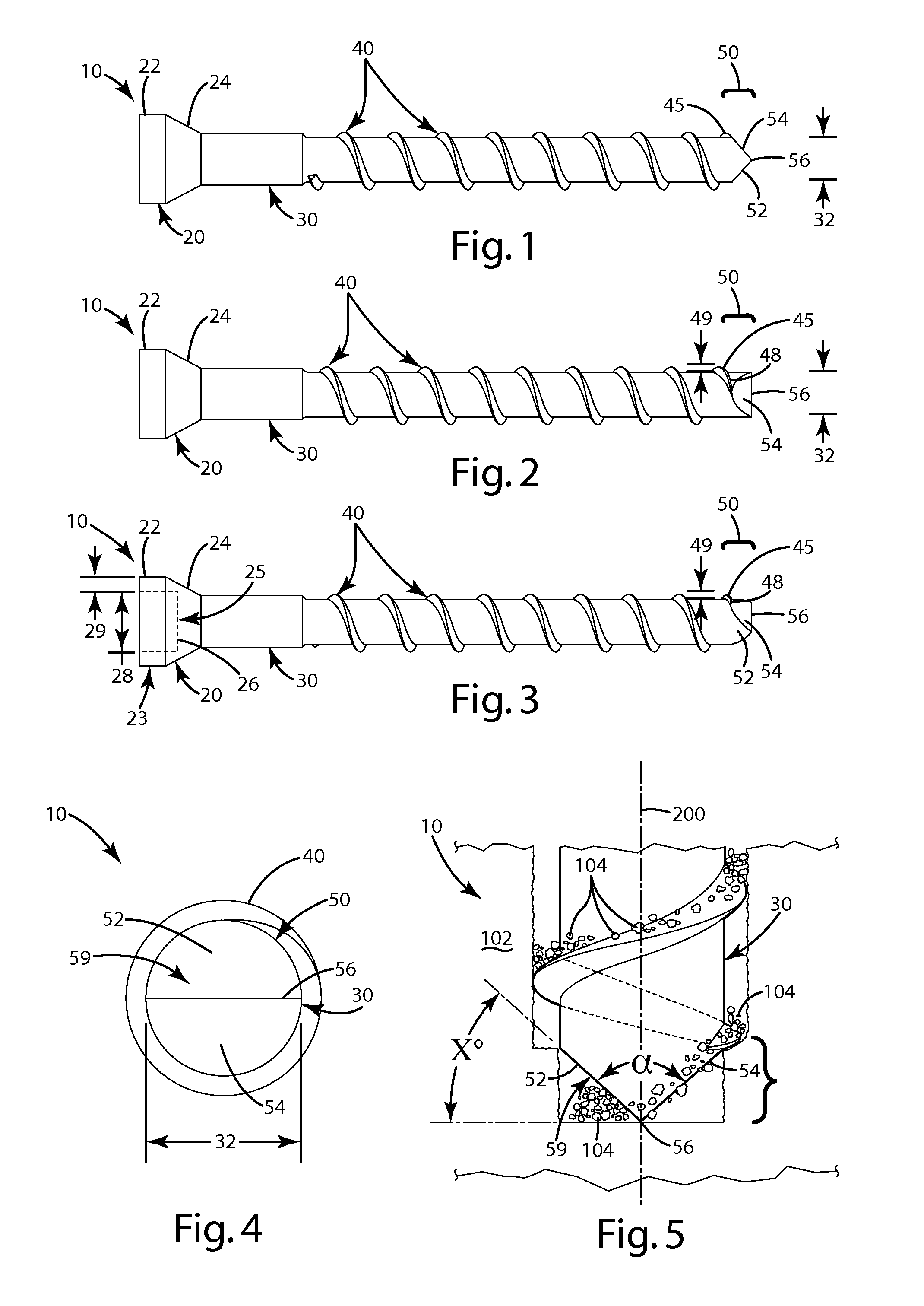
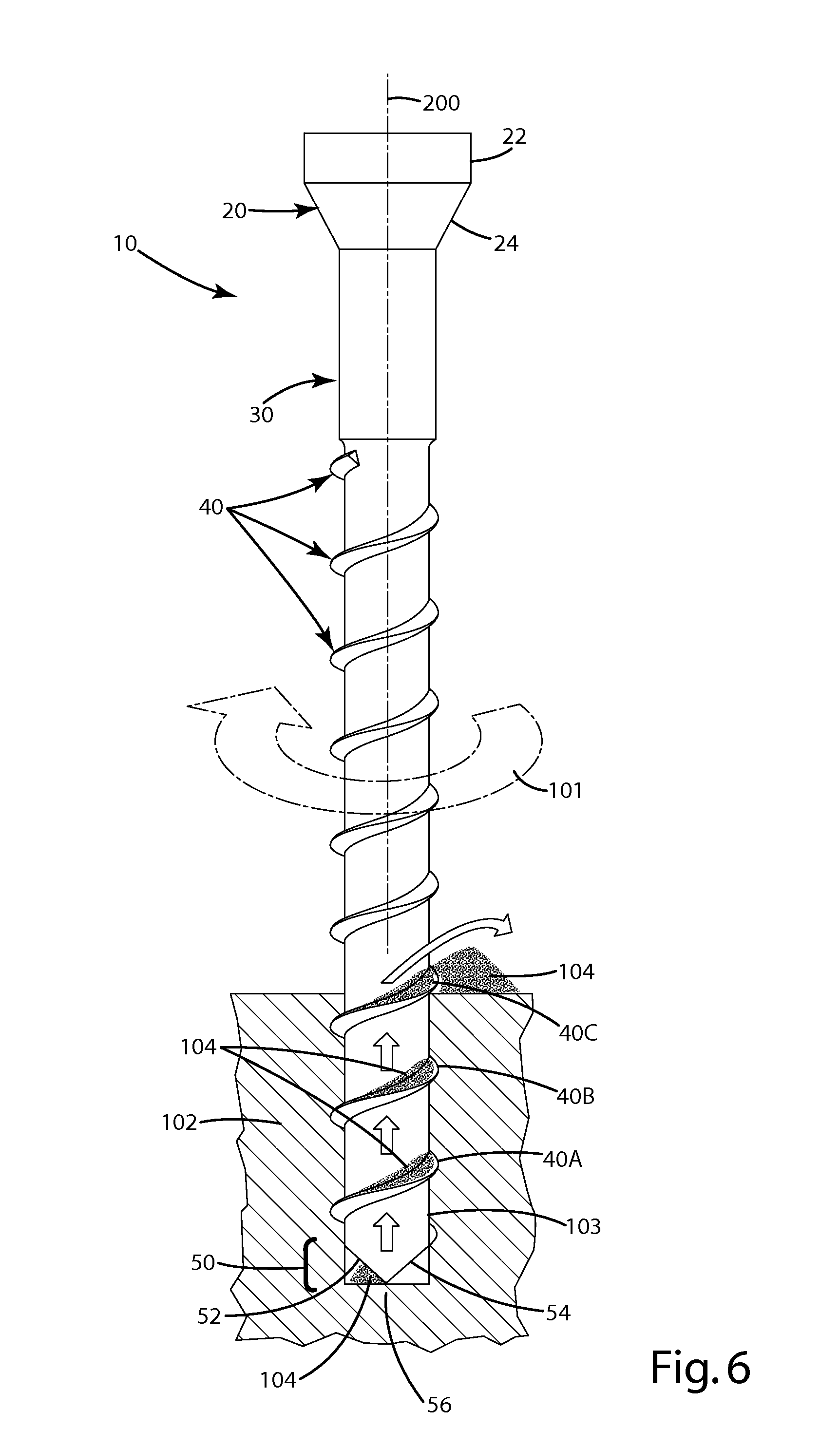
[0194]A current embodiment of a fastener is illustrated in FIGS. 1-6 and generally designated 10. The fastener can be in the form of a threaded fastener, and more particularly, a screw 10 including a head 20 and a shaft 30. The head can include an upper portion 22 and a lower portion 24. The upper portion 22 can be of a uniform diameter 23 (FIG. 3), which can range from about 0.197 to 0.202 inches in diameter, or can be of other dimensions if desired. The upper portion 22 of the head can be generally cylindrical and of a uniform diameter from the end of the head where the opening to the drive feature is located, to where the upper portion 22 begins to transition to the lower portion 24, where it tapers down to the shaft 30 of the screw 10. Optionally, the lower portion can be in the form of a frustoconical portion.

[0195]The upper portion 22 of the head 20 can define a screw drive feature, such as a star drive, a Phillips head drive or any other suitable drive. The screw drive featur...


PUM

PropertyMeasurementUnit
acute angleaaaaaaaaaa
obtuse angleaaaaaaaaaa

Abstract

A fastener installation tool and related method are provided for installing fasteners in boards. The tool can include a feed mechanism that automatically and sequentially feeds collated fasteners to a nose assembly. The nose assembly can include a guide having an alignment projection extending downwardly from the guide, and configured to engage a board corner and / or side surface, so as to align an angled bore through which fasteners are guided with the board corner and or side surface. The nose assembly can include a magnetic element located adjacent a path on which the collated fasteners are advanced. The magnetic element can exert a magnetic force on an individual fastener, aligning it for precise entry into the angled bore. The nose assembly can include a guide pocket to positively constrain a fastener as it rotates to ensure a desired advancement trajectory. A related method of installation is provided.

Description

BACKGROUND OF THE INVENTION[0001]The present invention relates to fasteners, and more particularly to a fastener, an installation tool and a related method of use.[0002]There are a variety of commercially available fasteners that are designed to fasten a work piece, such as a wooden board or a composite element, to a substrate, such as a subfloor, joist or other underlying support structure. In many cases, these fasteners are in the form of threaded screws including: a large, bugle-shaped head to which an installation drive attaches (for example, a Phillips or star drive screw head); a shaft that projects from the head; threads on the shaft, and a conical, sharpened point, which centers the screw on a location, and initially pierces the board so that the screw can advance into it. These types of screws are typically drilled downward, in an orthogonal manner, into the top of a board to fasten the board to an underlying support, such as a joist. Most of the holding power of such screw...

Claims


Application Information

Patent Timeline
Patent Type & Authority Patents(United States)
IPC IPC(8): B25B23/00F16B25/00F16B25/10
CPCB25B23/005B25B23/00F16B25/103F16B25/00F16B25/0015F16B25/0063F16B25/0073F16B25/0084
Inventor VANDENBERG, ROGER A.
Owner NAT NAIL
Why Eureka
Try Eureka