Display Device and Display Driving Method

a technology of a display device and a driving method, applied in the field of display technology, can solve problems such as degrading display quality, and achieve the effects of facilitating the use of narrow border designs, reducing the cost of display devices, and improving display qualities

Active Publication Date: 2011-07-14
AU OPTRONICS CORP
View PDF11 Cites 7 Cited by
  • Summary
  • Abstract
  • Description
  • Claims
  • Application Information

AI Technical Summary

Benefits of technology

[0024]In the above-mentioned embodiments of the present invention, by employing the pixel arrangement of at least three pixels serially connected with one by another, the display device can save ⅔ and even more data lines and thus the cost of the display device can be further reduced. Moreover, the above-mentioned embodiments can achieve better display qualities, for example, when the pixel arrangement of the display device takes three series-connected pixels as one cycle, since the arrangement of RGB three-colored pixels also takes three pixels as one cycle, the display driving for the display device still can be completed even if without the use of the driving means of alternately driving pixels arranged at two opposite sides of each data line and electrically coupled to the data line (hereinafter, termed as Zigzag driving), which makes it is easily to perform gamma curve correction for single color. Furthermore, since ⅔ and even more data lines can be saved, it is feasible that all of gate fan-out lines of the display device are arranged in the display area and no gate fan-out line is arranged in the border outside the display area, which facilitates the employment of narrow border designs and the uneven brightness issue resulting from the gate fan-out lines would not completely (i.e., only partially) be arranged in the display area no longer exists.

Problems solved by technology

However, the pixel arrangement of the above-mentioned display device with half-source driving structure takes two series-connected pixels as one cycle, since the arrangement of RGB three-colored pixels takes three pixels as one cycle, such pixel arrangement of taking two series-connected pixels as one cycle makes it is difficult to perform gamma curve correction for single color and thus a special driving means of driving the pixels arranged at two opposite sides of a data line and electrically coupled to the data line with Zigzag mode is necessary during the gamma curve correction, or else the color unevenness (e.g., line mura) would be caused to occur and the display quality is degraded.

Method used


Image

  • Display Device and Display Driving Method
  • Display Device and Display Driving Method
  • Display Device and Display Driving Method

Examples


Embodiment Construction

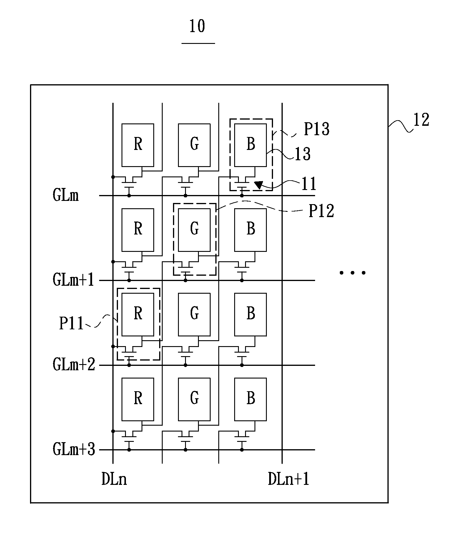
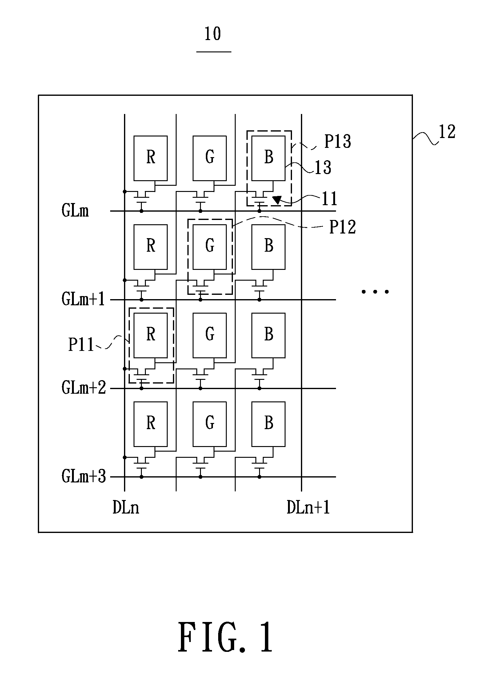
[0033]Referring to FIG. 1, a schematic partial view of a display device in accordance with an embodiment of the present invention is shown. The display device 10 includes a substrate 12, multiple gate lines Gm, Gm+1, Gm+2, Gm+3, multiple data lines DLn, DLn+1 and multiple pixels R, G, B. The gate lines Gm, Gm+1, Gm+2, Gm+3, the data lines DLn, DLn+1 and the pixels R, G, B all are formed on the substrate 12. The pixels R, G, B are colored pixels and arranged in a strip manner. The gate lines Gm, Gm+1, Gm+2, Gm+3 are for deciding whether to enable the pixels R, G, B. The data lines DLn, DLn+1 are for supplying display data to the pixels R, G, B for the purpose of image display. For the purpose of simplified description, hereinafter only three series-connected pixels P11, P12 and P13 are taken for an example to describe a pixel arrangement of the display device 10 in accordance with the embodiment of the present invention, in detail.

[0034]Still referring to FIG. 1, the gate line GLm+1 ...


PUM


Abstract

An exemplary display device includes multiple pixels, first through third gate lines and a data line. The pixels include first through third pixels. The first through third gate lines respectively are electrically coupled with the first through third pixels and for deciding whether to enable the first through third pixels. The first pixel is electrically coupled to the data line to receive a display data provided by the data line. The second pixel is electrically coupled to the first pixel to receive a display data provided by the data line through the first pixel. The third pixel is electrically coupled to the second pixel to receive a display data provided by the data line through both the first pixel and the second pixel. A display driving method adapted to be implemented in the display device also is provided.

Description

CROSS-REFERENCE TO RELATED APPLICATIONS[0001]This application is based upon and claims the benefit of priority from the prior Taiwanese Patent Application No. 098122242, filed Jul. 1, 2009, the entire contents of which are incorporated herein by reference.BACKGROUND[0002]1. Technical Field[0003]The present invention generally relates to display technology fields and, particularly to a display device and a display driving method.[0004]2. Description of the Related Art[0005]An active-type matrix display device generally includes a substrate, a gate driver(s), a source driver(s) and a plurality of pixels. The gate driver(s), the source driver(s) and the pixels are formed on the substrate. The gate driver(s) is / are for generating gate driving signals and supplying the gate driving signals to a plurality of gate lines through gate fan-out lines to decide whether to enable the pixels electrically coupled with the gate lines. The source driver(s) is / are for supplying the pixels with displa...

Claims


Application Information

Patent Timeline
Patent Type & Authority Applications(United States)
IPC IPC(8): G09G3/20G09G5/00
CPCG09G3/3648G09G3/3677G09G2300/0426G09G2310/08G09G2310/0205G09G2310/0251G09G2310/06G09G2300/0443
Inventor CHEN, YU-CHENGCHIANG, YI-CHENLIU, CHUN-TING
Owner AU OPTRONICS CORP
Why Eureka
Try Eureka