Soldering iron tip
a technology of iron tip and spherical tip, which is applied in the direction of spherical tip, non-electric welding apparatus, manufacturing tools, etc., can solve the problem of non-uniform heating
- Summary
- Abstract
- Description
- Claims
- Application Information
AI Technical Summary
Benefits of technology
Problems solved by technology
Method used
Image
Examples
first embodiment
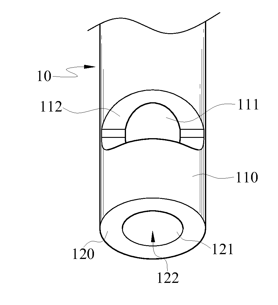
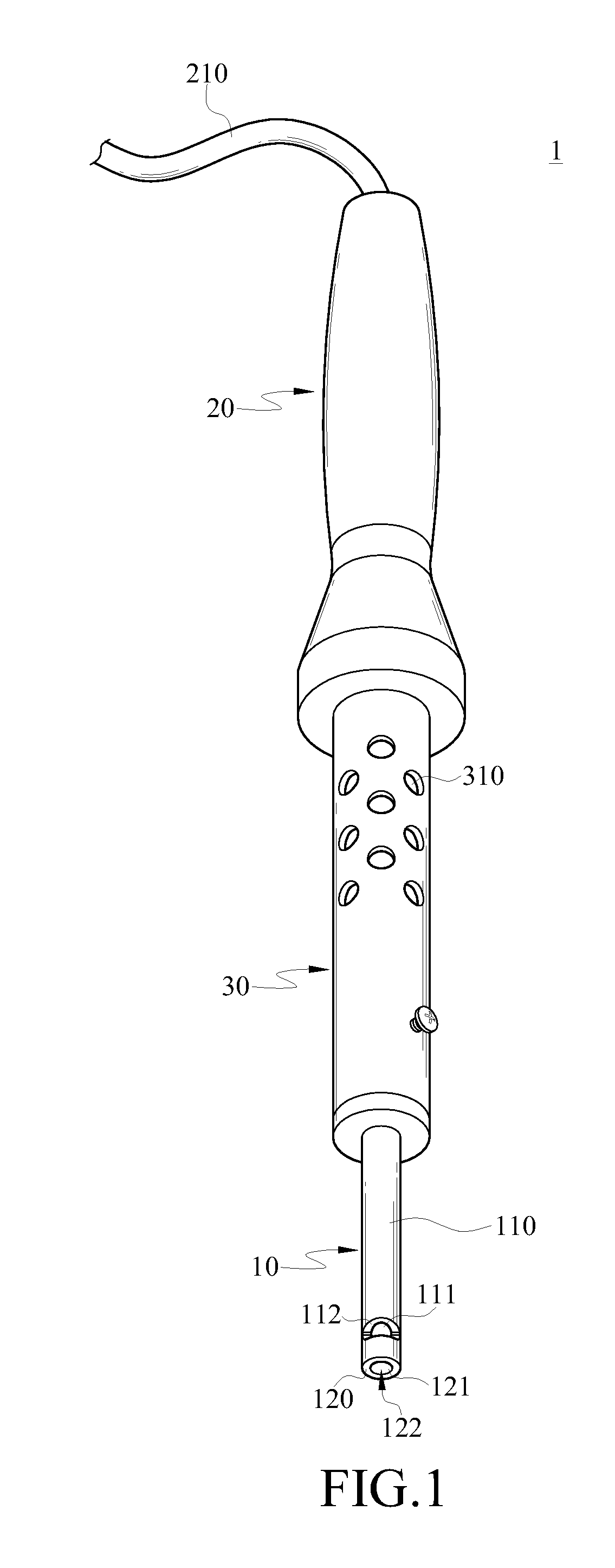
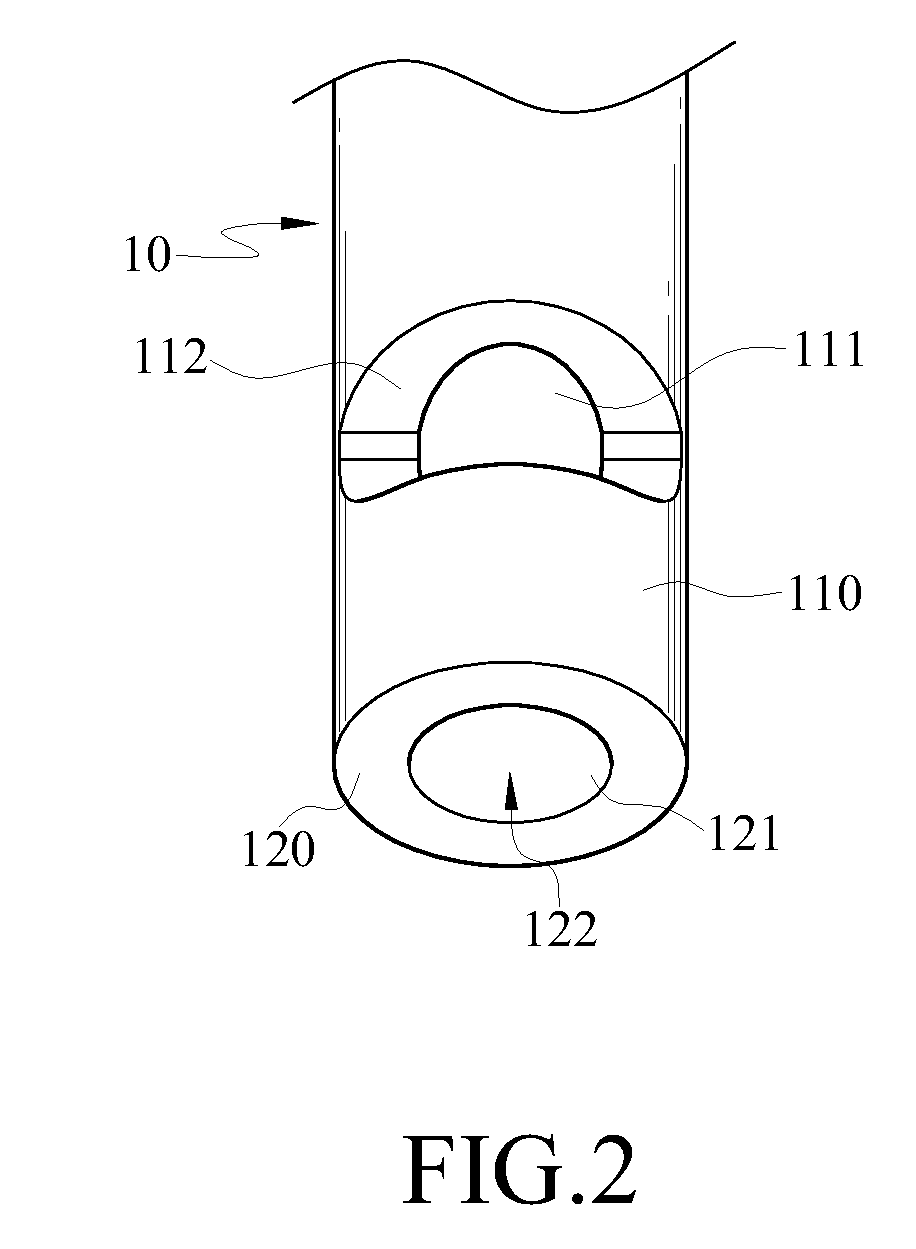
[0025]Referring to FIGS. 1 and 2, a soldering iron tip 10 provided in the present invention is disposed on an electric soldering iron 1. Besides the soldering iron tip 10, the electric soldering iron 1 further comprises a handle 20 and a metal shell 30. One end of the handle 20 is disposed with an electric wire 210, and the other end of the handle 20 is connected to the metal shell 30. The electric wire 210 is configured to be connected to a heater (not shown), and used for transferring electric energy supplied by the heater to the metal shell 30. A plurality of heat-dissipation holes 310 is opened in the metal shell 30, and a plurality of coils (not shown) is accommodated in the metal shell 30 and used for converting the electric energy transferred to the metal shell 30 into heat energy.
[0026]One end of the soldering iron tip 10 is inserted into the metal shell 30, and the soldering iron tip 10 has a side surface 110. The side surface 110 extends from the end of the soldering iron ...
second embodiment
[0034]Moreover, as shown in FIGS. 6 and 7, in the second embodiment, the end surface 120 of the soldering iron tip 10 may also be disposed on the soldering iron tip 10 in an inclined manner, that is, the end surface 120 forms an angle of smaller than or larger than 90 degrees with respect to the side surface 110, instead of being perpendicular to the side surface 110. Therefore, the solder bar 50 is inserted into the channel 122 through the through hole 111 or the guide hole 121. In addition, the molten solder formed by the solder bar 50 is also wrapped and blocked by the soldering iron tip 10 and confined to the area of the workpiece 410 covered by the channel 122, thereby preventing the molten solder from flowing to areas outside the workpiece 410.
[0035]Referring to FIGS. 8 and 9, the soldering iron tip 10 provided in a third embodiment of the present invention is applied in a hot tweezer-type electric soldering iron 6. The hot tweezer-type electric soldering iron 6 comprises two ...
third embodiment
[0037]One end of the soldering iron tip 10 provided in the present invention is inserted into the metal shell 620, and the soldering iron tip 10 has a side surface 110. The side surface 110 extends from the end of the soldering iron tip 10 inserted into the metal shell 620 towards the other end of the soldering iron tip 10 opposite to the metal shell 620. Meanwhile, the other end of the soldering iron tip 10 opposite to the metal shell 620 has an end surface 120. The side surface 110 of the soldering iron tip 10 surrounds the edge of the end surface 120, so that the side surface 110 is connected to the end surface 120 in an approximately perpendicular manner. A cutting plane 113 connected to the end surface 120 is formed at a position of the side surface 110 adjacent to the end surface 120.
[0038]The end surface 120 has a guide hole 121, and the guide hole 121 is opened in the end surface 120 along an axial direction of the soldering iron tip 10. The axial direction means that the gu...
PUM
| Property | Measurement | Unit |
|---|---|---|
| angle | aaaaa | aaaaa |
| diameter | aaaaa | aaaaa |
| electric energy | aaaaa | aaaaa |
Abstract
Description
Claims
Application Information
 - R&D
- Intellectual Property
- Life Sciences
- Materials
- Tech Scout
- Unparalleled Data Quality
- Higher Quality Content
- 60% Fewer Hallucinations
Browse by: Latest US Patents, China's latest patents, Technical Efficacy Thesaurus, Application Domain, Technology Topic, Popular Technical Reports.
© 2025 PatSnap. All rights reserved.Legal|Privacy policy|Modern Slavery Act Transparency Statement|Sitemap|About US| Contact US: help@patsnap.com


