
Cerebrospinal fluid drainage

a cerebrospinal fluid and percutaneous adjustment technology, applied in the direction of wound drains, intravenous devices, medical devices, etc., can solve the problems of uncontrollable discharge, increased risk of infection in external drainage, and no longer justified external drainage after seven to ten days, so as to achieve the effect of reducing the weight of the closing element and facilitating design freedom

Inactive Publication Date: 2011-07-07
CHRISTOPH MIETHKE
View PDF100 Cites 3 Cited by
  • Summary
  • Abstract
  • Description
  • Claims
  • Application Information

AI Technical Summary

Benefits of technology

[0013]An object of the present application is to take account of the clinical situations and to minimize stress to the patient.SUMMARY

Problems solved by technology

An uncontrolled discharge is just as dangerous as an excessive pressure.
External drainages have a rapidly increasing risk of infection as a function of the duration of the treatment.
In view of the extremely high risk of infection, an external drainage can no longer be justified after seven to ten days.
Internal drainage by means of a shunt system has a high risk of blockage by blood components in the cerebrospinal fluid.
Considering the low pressures that are encountered with a limited clearance between the rotary slider and the inner side of the housing, a gasket is unnecessary and / or not desired.
A self-activating brake may then be unnecessary and are not desired.

Method used


Image

  • Cerebrospinal fluid drainage
  • Cerebrospinal fluid drainage
  • Cerebrospinal fluid drainage

Examples


Embodiment Construction

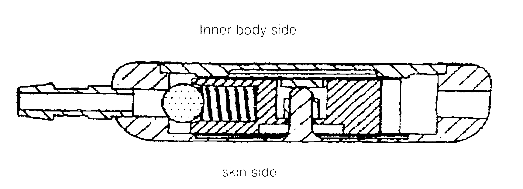
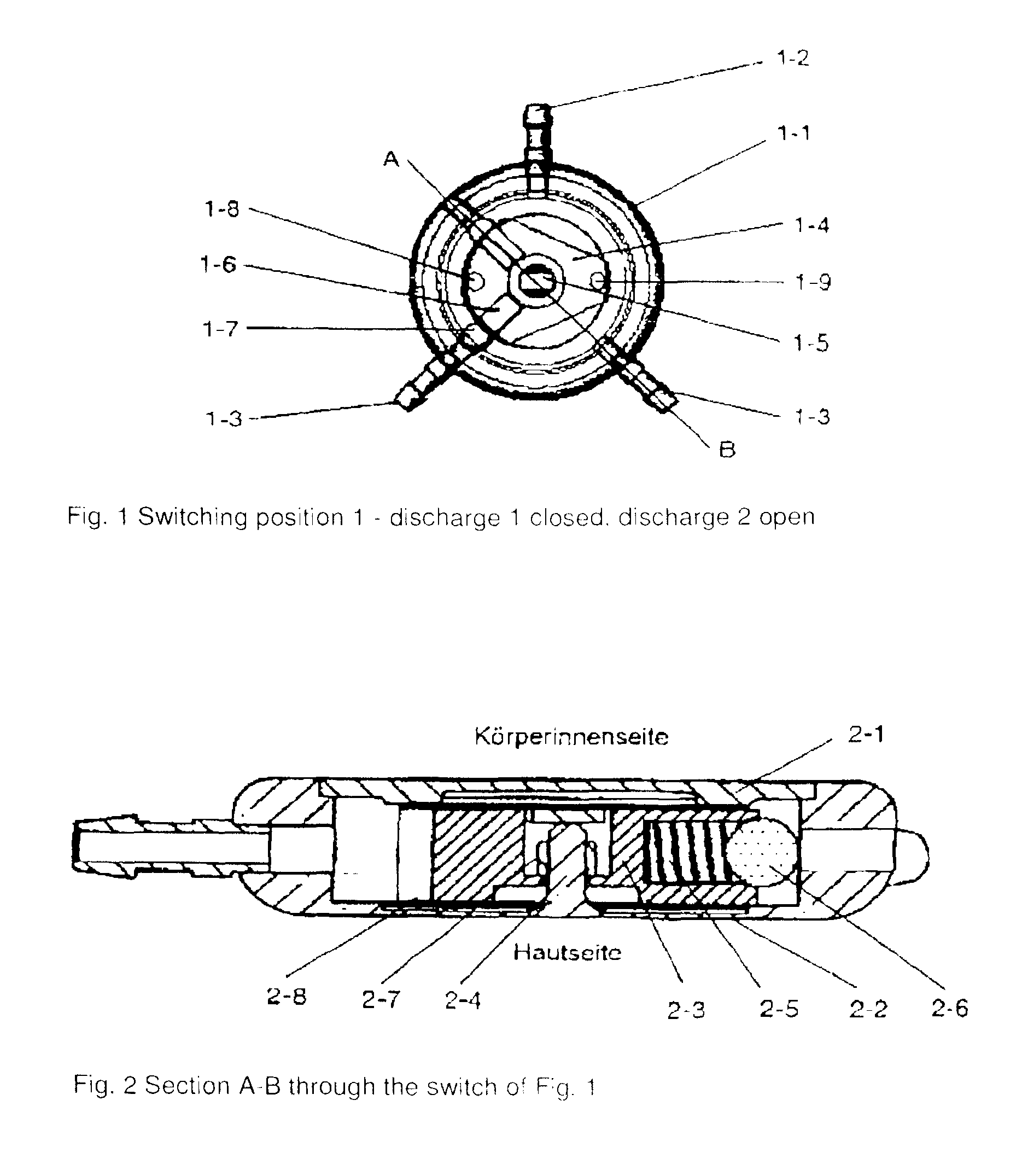
[0078]In the drawing of FIG. 1 an embodiment of the present application is illustrated in the switch position 1 (discharge 1 closed, discharge 2 open).

[0079]In the drawing of FIG. 2 is illustrated the view of the section A-B of the switch of FIG. 1.

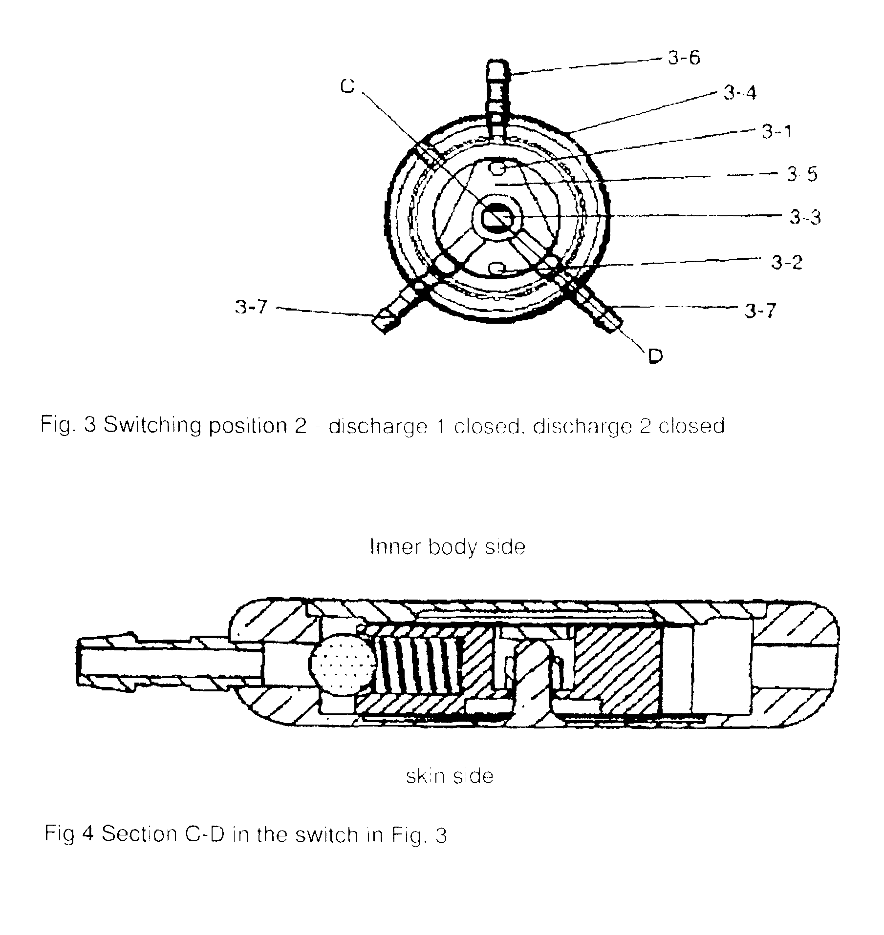
[0080]The two-way discharge switch comprises a solid metallic housing 1-1, a lid 1-2, a base 2-2 as well as an inlet port 1-2 and outlet port 1-3. Moreover, in the embodiment, the 2-way discharge switch possesses a closing element 1-4 / 2-3 that is mounted on the shaft 1-5 / 2-4, a spring system 1-6 / 2-5 with a ball 1-7 / 2-6 for the precision non-return valve and a locking device 2-7. The two-way discharge switch is located in a tube that is implanted in a patient for cerebrospinal fluid drainage. The two-way discharge switch has three switching states. Switching state 1 closes discharge 1 and opens discharge 2, switching state 2 closes both discharges 1 and 2, and switching state 3 closes discharge 2 and opens discharge 1. In the switching sta...


PUM


Abstract

A cerebrospinal fluid drainage. The abstract of the disclosure is submitted herewith as required by 37 C.F.R. §1.72(b). As stated in 37 C.F.R. §1.72(b): A brief abstract of the technical disclosure in the specification must commence on a separate sheet, preferably following the claims, under the heading “Abstract of the Disclosure.” The purpose of the abstract is to enable the Patent and Trademark Office and the public generally to determine quickly from a cursory inspection the nature and gist of the technical disclosure. The abstract shall not be used for interpreting the scope of the claims. Therefore, any statements made relating to the abstract are not intended to limit the claims in any manner and should not be interpreted as limiting the claims in any manner.

Description

CONTINUING APPLICATION DATA[0001]This application is a Continuation-In-Part application of International Patent Application No. PCT / EP2009 / 004751, filed on Jul. 1, 2009, which claims priority from Federal Republic of Germany Patent Application No. 10 2008 030 942.7, filed on Jul. 2, 2008. International Patent Application No. PCT / EP2009 / 004751 was pending as of the filing date of this application. The United States was an elected state in International Patent Application No. PCT / EP2009 / 004751.BACKGROUND[0002]1. Technical Field[0003]The present application relates to a percutaneously adjustable drainage system for cerebrospinal fluid.[0004]2. Background Information[0005]Background information is for informational purposes only and does not necessarily admit that subsequently mentioned information and publications are prior art.Initial Situation:[0006]Cerebrospinal fluid drainage is required and / or desired for example for hemorrhages resulting from a head injury or for cerebral hemorrh...

Claims


Application Information

Patent Timeline
IPC IPC(8): A61M1/00
CPCA61M27/006A61M2210/0693A61M2202/0464
Inventor MIETHKE, CHRISTOPHMEIER, ULLRICH
Owner CHRISTOPH MIETHKE
Learn More