
Radio access point testing apparatus

a testing apparatus and access point technology, applied in the field of radio access point testing apparatus, can solve the problems of high transmission power, test might fail in a calling connection, and difficulty in discriminating whether the transmission power is high

Active Publication Date: 2011-07-07
FIPA FROHWITTER INTPROP AG
View PDF9 Cites 18 Cited by
  • Summary
  • Abstract
  • Description
  • Claims
  • Application Information

AI Technical Summary

Benefits of technology

"The patent text describes a problem in testing the normalcy of a radio access point using a testing terminal. When there is a high level of interference or noise in the environment, the testing terminal may fail to connect to the access point and the normalcy confirming test may fail as well. The invention aims to provide a solution that excludes the influence of external noise and can carry out the testing of the radio access point even under such conditions."

Problems solved by technology

On this occasion, it is difficult to discriminate whether the high transmission power is influenced by the external noise or is caused by the radio characteristic degradation of the access point.
As one of the problems (the first problem), the test might fail in a calling connection for the reason that an originating signal from the testing terminal does not reach the access point.

Method used


Image

  • Radio access point testing apparatus
  • Radio access point testing apparatus
  • Radio access point testing apparatus

Examples


second embodiment

2. Second Embodiment

[0098]FIG. 3 shows the configuration of the second resolution means for the second problem. In this embodiment, a test is performed using a test signal in which thermal noise, for example, is superposed on the test signal itself, and which is set at a signal quality that will satisfy a desired PER or S / N (signal-to-noise ratio). A terminal function portion has its transmission power raised by superposing the thermal noise, in order to control the transmission power so that the S / N, for example, may become constant.

[0099]In the first embodiment, the noise component in the case of evaluating the signal quality of the test signal is predominated by the external noise component. Therefore, in a case where the external noise fluctuates temporally, the precision of a measurement result sometimes degrades. In contrast, in the second embodiment, the noise of known level is added as the test signal, and hence, a signal quality can be measured without being influenced by t...

first embodiment

3. Modification to First Embodiment

[0104]As the other means (second means) for solving the first problem, the access terminal of a general user calculates the initial transmission power by Formula (1) mentioned before, whereas the initial transmission power of the testing access terminal 109 is not evaluated by Formula (1), but it is given as a fixed value which is the optimum value evaluated from the path loss between the radio access point 104 and the testing access terminal 109. Since the path loss between the testing access terminal 109 and the radio access point 104 does not change with time, this means can be adopted. Besides, on this occasion, in a case where the RSSI (X) of the forward link has risen to exceed a threshold value, on account of the external noise or the like, the initial transmission power (Xo) given as the fixed value is raised by an offset component (ΔX) corresponding to the rise of the RSSI of the forward link (to Xo+ΔX), whereby the initial transmission po...


PUM


Abstract

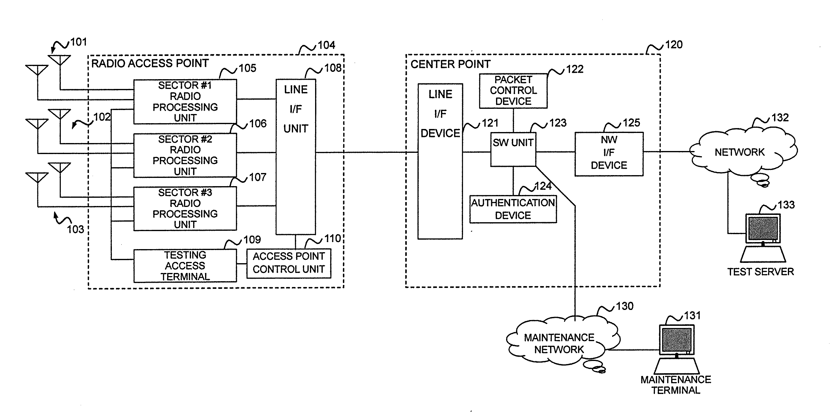
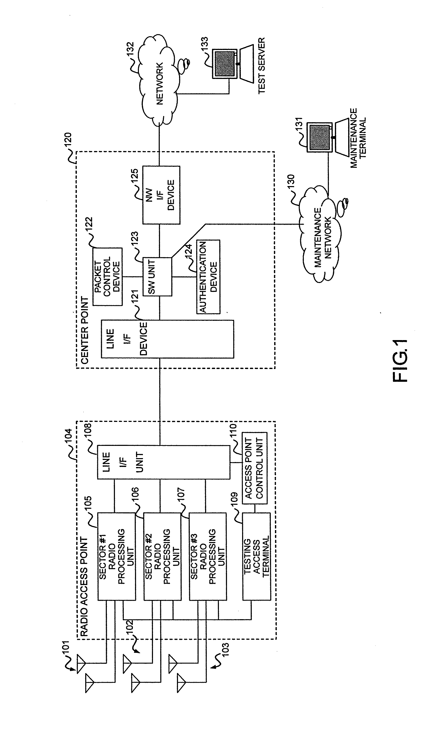
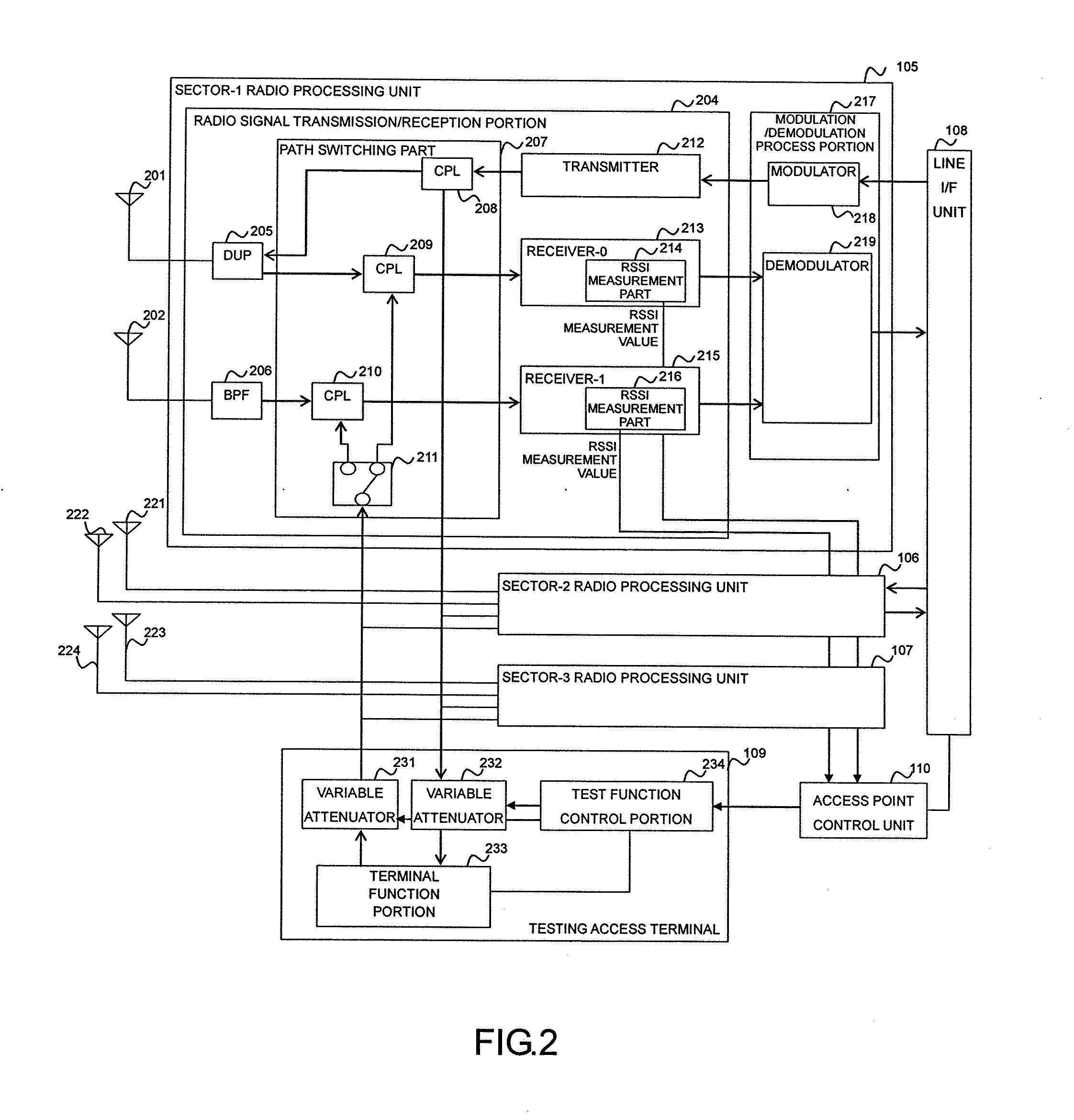
In a case where reception power in a radio access point is high by external noise, the normalcy of the radio access point is tested. In order to judge the normalcy of the radio characteristic of the radio access point, a test is performed through the calling connection between a testing access terminal in the radio access point and a predetermined device. An RSSI is measured before and after the transmission of a test signal. When the RSSI exceeds a threshold value, the path loss of a reverse link connected from the radio access point to the testing access terminal is increased by an attenuator. Then, reception power in the testing access terminal decreases. Thus, initial transmission power in accordance with the reception power from the testing access terminal is raised and the calling connection of the testing access terminal can be performed even under the external noise.

Description

CROSS REFERENCE TO RELATED APPLICATION[0001]This is a continuation of U.S. application Ser. No. 11 / 758,088, filed Jun. 5, 2007. This application relates to and claims priority from Japanese Patent Application No. 2006-160862, filed on Jun. 9, 2006. The entirety of the contents and subject matter of all of the above is incorporated herein by reference.BACKGROUND OF THE INVENTION[0002]The present invention relates to a radio access point testing apparatus, and more particularly to a radio access point testing apparatus which confirms the normalcy of the radio characteristic of a radio access point in an environment where interfering waves such as external noise mix into the radio access point in a mobile communication system employing a CDMA format.[0003]In servicing the mobile communication system, the stability of the system is one of important factors. For the stable operation of the system, it is required to prevent the occurrence of any failure leading to a system service shutdow...

Claims


Application Information

Patent Timeline
Patent Type & Authority Applications(United States)
IPC IPC(8): H04L12/26H04B1/707H04J13/00H04W24/00H04W24/06H04W28/04H04W52/10H04W52/20H04W52/24H04W52/50H04W76/02H04W88/08
CPCH04W24/06H04W28/04H04W52/20H04W52/24H04W88/08H04W52/245H04W52/50H04W76/02H04W52/243H04W76/10
Inventor KAWAMOTO, KIYOSHIYOSHIDA, AKIHIKO
Owner FIPA FROHWITTER INTPROP AG
Learn More