Precise compensation of video propagation duration

a video propagation and precise compensation technology, applied in the field of synchronization of data delivery, can solve the problems of delay in path, jitter disrupting stream continuity, and disparity of path delays

Inactive Publication Date: 2011-07-07
THOMSON LICENSING SA
View PDF3 Cites 19 Cited by
  • Summary
  • Abstract
  • Description
  • Claims
  • Application Information

AI Technical Summary

Problems solved by technology

The problem is how to recombine these signals at the extractor devices level in the presence of the following disruptive elements: network jitter and the different delays of different data paths.
The jitter disrupts the continuity of the stream at the point of reconstruction.
There is also a disparity of the path delays, even a maximal delay defined in the standard 802.1 AVB is 2 ms for a complex infrastructure, and the limits of current processing equipment (SDI or AES switcher, SDI or AES router) leads to alignment issues which have an impact on the recombination (Audio / Video lip sync).

Method used


Image

  • Precise compensation of video propagation duration
  • Precise compensation of video propagation duration
  • Precise compensation of video propagation duration

Examples


Embodiment Construction

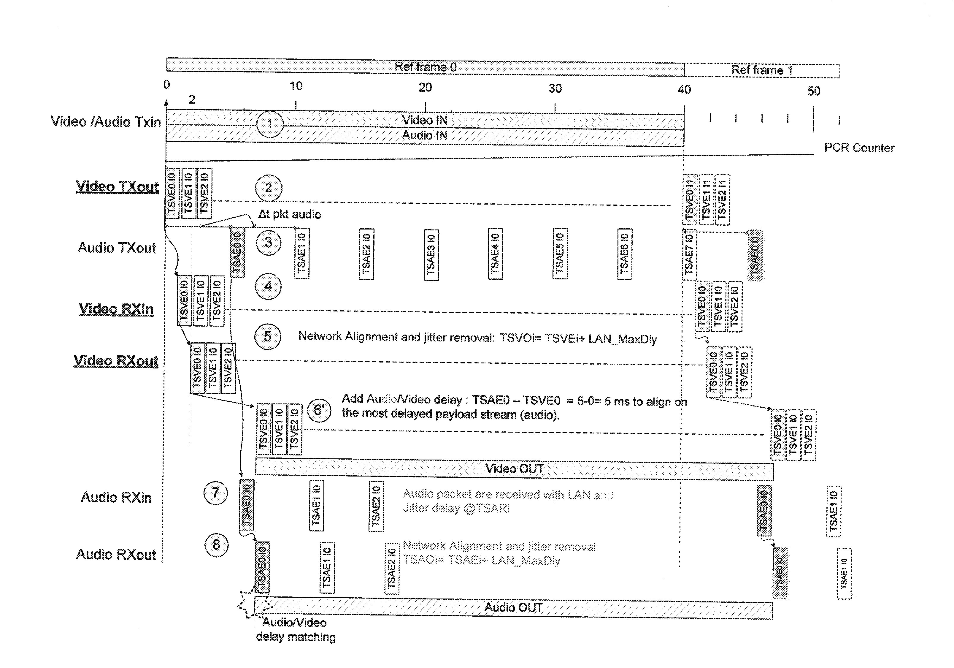
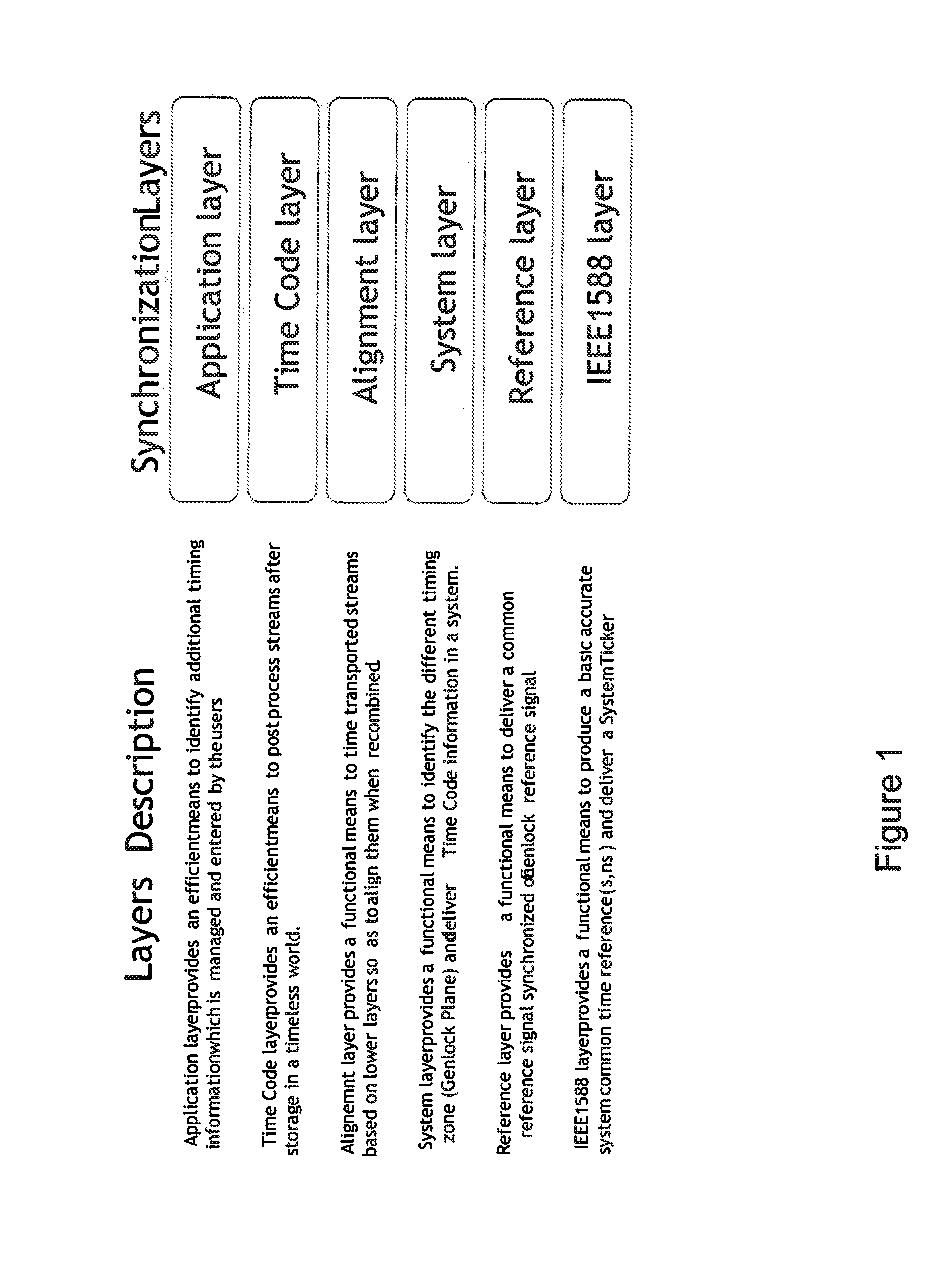
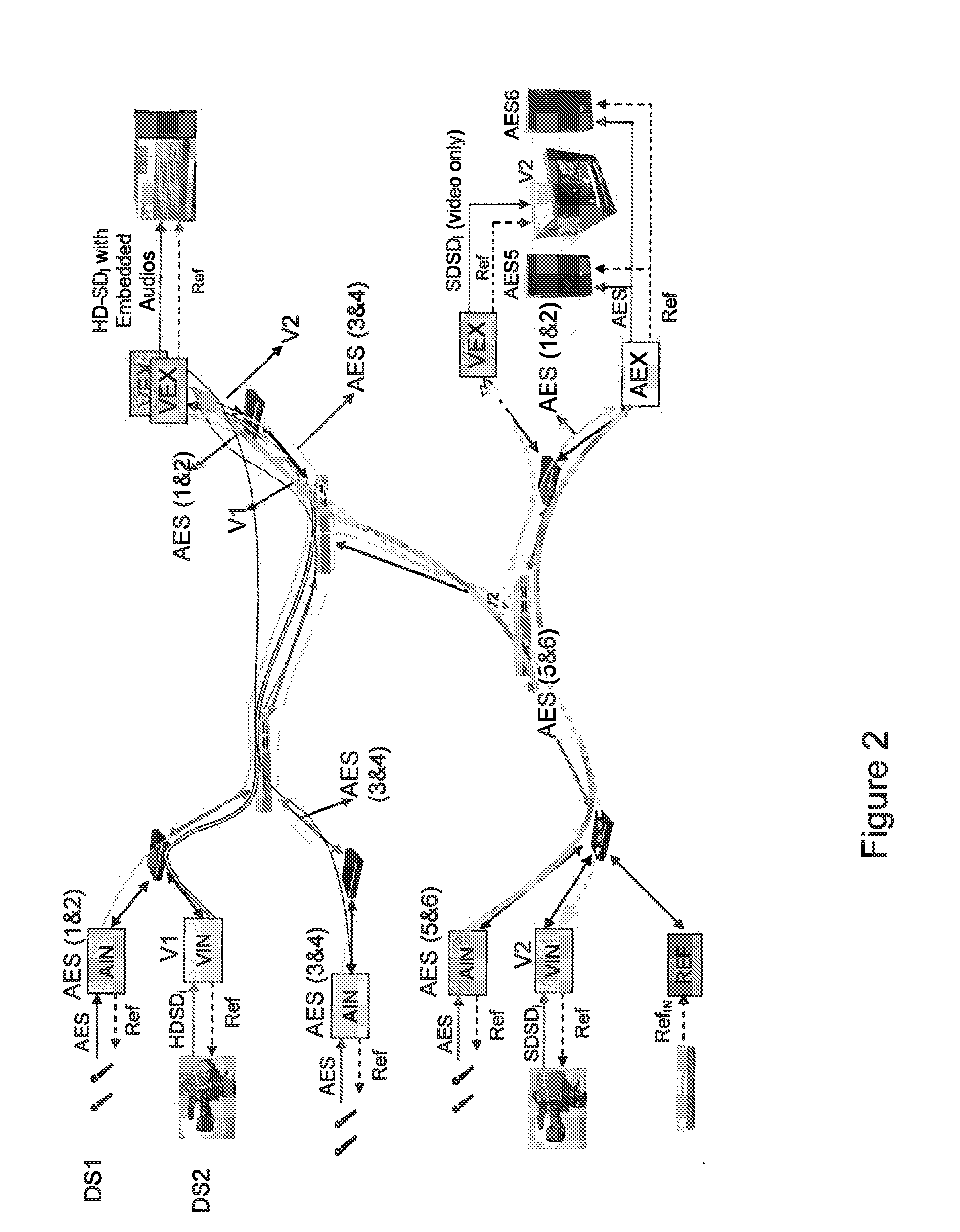
[0045]The appended drawings may serve not only to complete the invention, but also to contribute to its definition, if need be.

[0046]The temporal marking must use the same time base on the emitter and receiver devices.

[0047]This is ensured by the local reference counter (PCR) which is recovered and synchronous on all the devices deployed on the packet switched network. The reference counter value is proposed to be placed in the RTP Time Stamp field of the RTP header. Based on the length of this counter, which is not defined yet, it should be possible to standardize a new RTP header

[0048]On the transmitter side, a temporal marker TSEi must be created at the appropriate instant to avoid adding additional jitter. This is the instant when the RTP payload is ready to be sent. After this moment, an arbitration mechanism is implemented to prioritize the different flows which are processed by the devices (Best effort, Network System Management, Video, Audio, . . . ). This process introduces...


PUM


Abstract

The invention relates to the field of the synchronization of data delivery onto equipments connected over a packet switching network, in particular when the equipments are devoted to video and audio data or Auxiliary data linked to processing and are connected over a local area network for forming a video / audio production studio.More precisely the invention concerns a data inserter device for inserting a timestamp in packets, and a delay compensating device for extracting said timestamp and compensating the delivery delay and in particular the jitter, the network delay and the packet generation duration or any additional user delay.

Description

BACKGROUND OF THE INVENTION[0001]1. Field of the Invention[0002]The invention relates to the field of the synchronization of data delivery onto equipments connected over a packet switching network, in particular when the equipments are devoted to video and audio data processing and are connected over a local area network for forming a video / audio production studio. More precisely the invention concerns a data inserter device for inserting a timestamp in packets, and a delay compensating device for extracting said timestamp and compensate the delivery delay and in particular the jitter, the network delay and the packet generation duration.[0003]2. Description of the Prior Art[0004]Future production environment will move forward using Ethernet technology. This architecture may provide enhancements in the current data stream alignment mechanism which are crucial for video production applications.[0005]This architecture is based on a Local Area Network, which implements only Ethernet sw...

Claims


Application Information

Patent Timeline
Patent Type & Authority Applications(United States)
IPC IPC(8): H04N5/06
CPCH04J3/0661H04N21/4307H04L65/80H04L65/605H04L65/607H04N21/8547H04N21/43072H04L65/765H04L65/70
Inventor HARDY, PATRICKDERRIEN, BRUNOPROVOST, BERTRANDMARLEC, OLIVIERPRIOUL, HUBERT
Owner THOMSON LICENSING SA
Why Eureka
Try Eureka