
Compensation of motion in a moving organ using an internal position reference sensor

Active Publication Date: 2011-06-30
ST JUDE MEDICAL INT HLDG SARL
View PDF8 Cites 83 Cited by
  • Summary
  • Abstract
  • Description
  • Claims
  • Application Information

AI Technical Summary

Benefits of technology

[0007]One advantage of the methods and apparatus described, depicted and claimed herein relates to the ability to accurately compensate for the motion of a moving region of interest in a patient's body (e.g., a moving organ such as the heart), such as may be needed when superimposing a representation of a catheter tip on an image acquired at a time different than a time when the position of the catheter tip was acquired.

Problems solved by technology

For example only, in the case of atrial fibrillation, the ECG signal may not effectively serve as a predictor or correlation input for the motion of the atria.

Method used


Image

  • Compensation of motion in a moving organ using an internal position reference sensor
  • Compensation of motion in a moving organ using an internal position reference sensor
  • Compensation of motion in a moving organ using an internal position reference sensor

Examples


Embodiment Construction

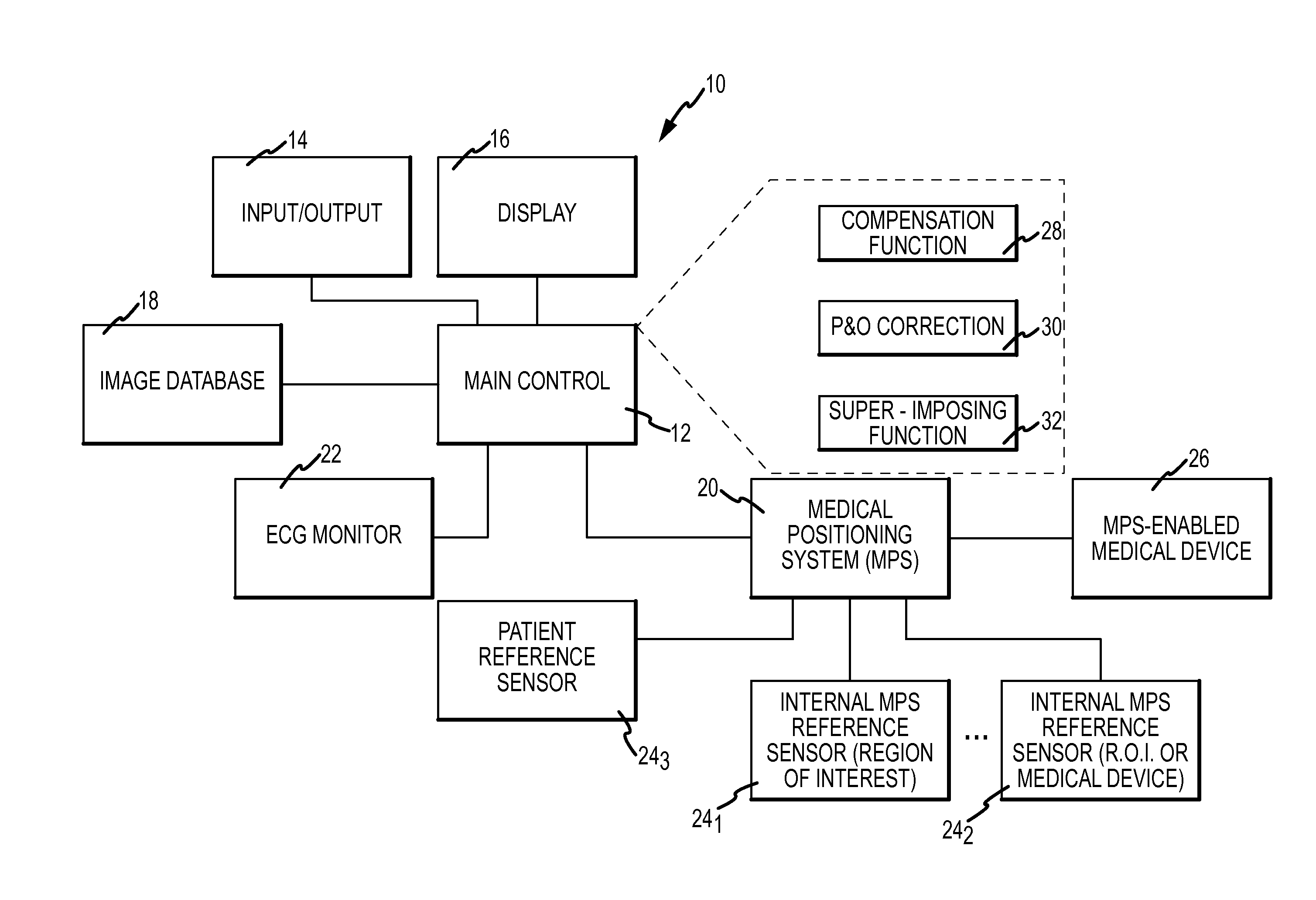
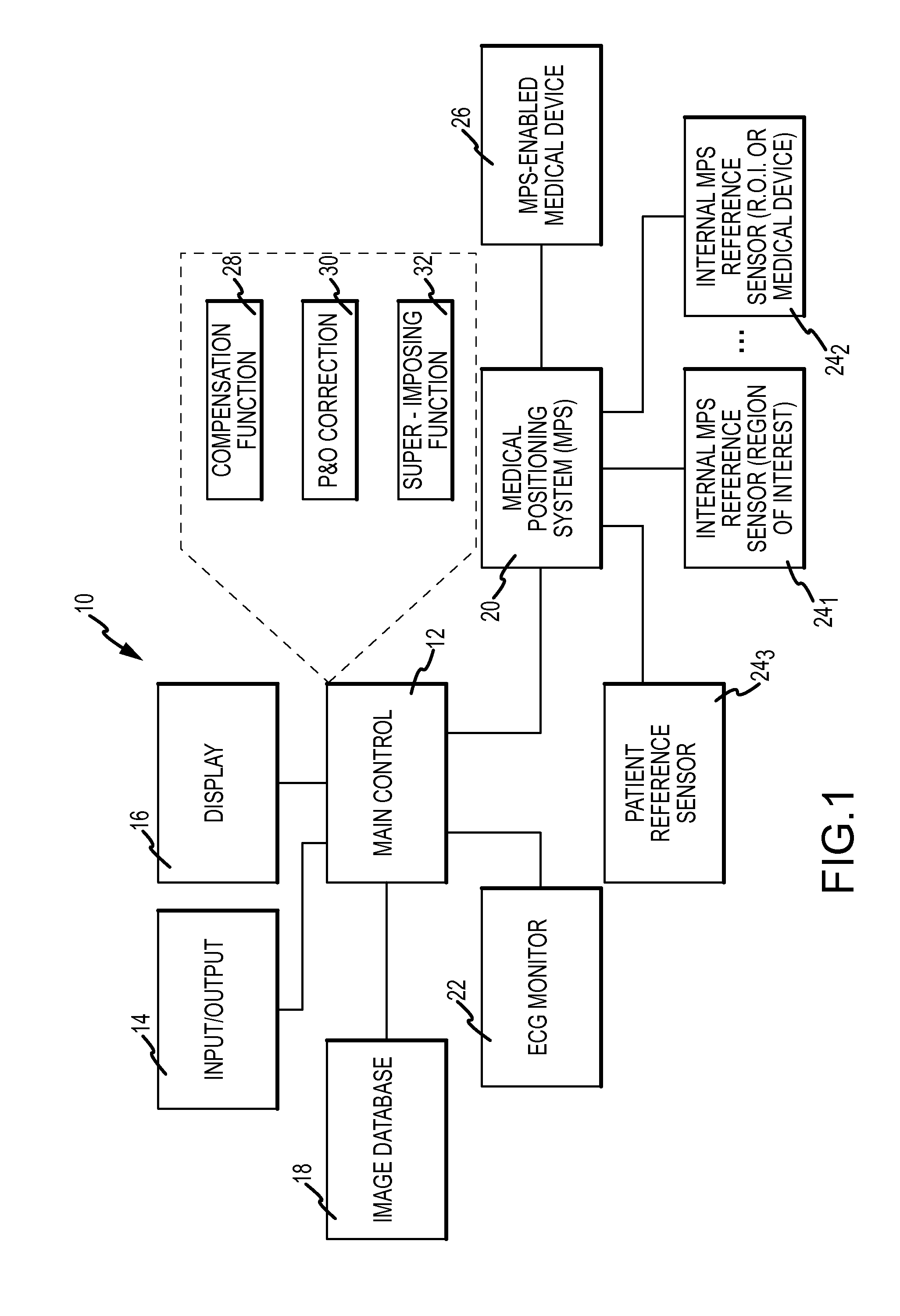
[0016]Referring now to the drawings wherein like reference numerals are used to identify identical components in the various views, FIG. 1 is a diagrammatic view of a system 10 in which aspects of the invention may be embodied. It should be understood that while embodiments of the invention will be described in connection with a magnetic field-based positioning system deployed in connection with a fluoroscopy-based imaging system, such an embodiment is exemplary only and not limiting in nature.

[0017]Before proceeding to a detailed description keyed to the drawings, a general overview concerning motion compensation will be set forth. As a starting point, there is a desire to reduce a patient's exposure to x-rays, such as may be used in fluoroscopy. It is therefore desirable to be able to use, and reuse to the greatest extent possible, an image (or a sequence of images defining a cine loop) of a region of interest acquired in the past. This will reduce the need for continuous exposure...


PUM


Abstract

An apparatus for displaying a moving region of interest located within a body includes a positioning system to determine a position and orientation (P&O) of a medical device as well as to track, using an internal position reference sensor, the motion of the region of interest over time. A compensation function block generates a motion compensation function based on the motion of the region of interest, which is configured to compensate for the motion of the region of interest between a first time, for example a time at which an image was acquired and a second time, for example a time at which a P&O of the device was measured. The measured P&O is corrected using the compensation function. A representation of the medical device is superimposed on the image in accordance with the corrected P&O.

Description

BACKGROUND OF THE INVENTION[0001]a. Field of the Invention[0002]The instant invention relates generally to medical imaging and navigation and more particularly to a system and method for compensation of motion in a moving organ using an internal reference sensor.[0003]b. Background Art[0004]Systems and methods for obtaining and displaying two-dimensional and three-dimensional images are known in the art, for example, as seen by reference to U.S. Pat. No. 7,386,339 entitled “MEDICAL IMAGING AND NAVIGATION SYSTEM” to Strommer et al., hereby incorporated by reference in its entirety. Strommer et al. disclose a medical imaging and navigation system that has a capability for constructing and displaying three-dimensional images of moving organs, synchronously with the actual movement of these organs and synchronously with an invasive surgical tool, such as a catheter. The system includes a medical positioning system (MPS) for ascertaining the location and orientation of multiple MPS senso...

Claims


Application Information

Patent Timeline
IPC IPC(8): G06K9/00A61B6/00
CPCA61B6/12A61B6/527A61B19/5244A61B2017/00703A61B2019/5238A61B2019/5251A61B2019/5483H04L27/3405G06T7/0028G06T2207/10121G06T2207/30021G06T2207/30048A61B6/503A61B6/5235A61B6/5264A61B2090/3983A61B34/20A61B2090/376A61B2034/2051G06T7/33
Inventor COHEN, AMITEICHLER, UZIIZMIRLI, ALON
Owner ST JUDE MEDICAL INT HLDG SARL
Learn More