
Electronic apparatus and projector

Inactive Publication Date: 2011-06-30
QUISDA CORP
View PDF25 Cites 37 Cited by
  • Summary
  • Abstract
  • Description
  • Claims
  • Application Information

AI Technical Summary

Benefits of technology

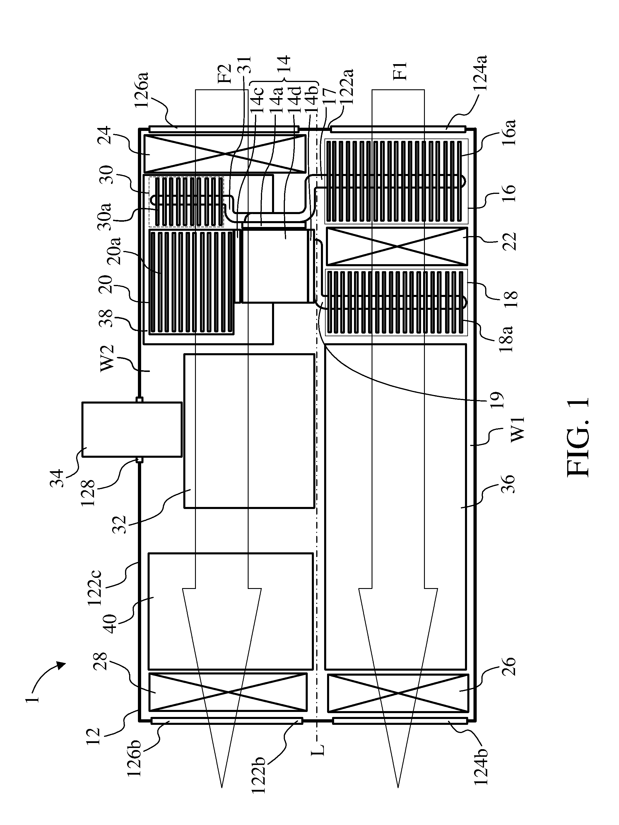
[0008]The electronic apparatus of the invention includes a casing, an optical module, a first heat-dissipation device, a second heat-dissipation device, and a first fan. The casing includes a first air-inlet and a first air-outlet, wherein a first passage is formed between the first air-inlet and the first air-outlet. The optical module is disposed in the casing; the optical module has a first light source and a second light source. The first heat-dissipation device is disposed on the first passage and connected to the first light source. The second heat-dissipation device is disposed on the first passage and connected to the second light source. The first fan is disposed between the first heat-dissipation device and the second heat-dissipation device on the first passage. The first fan generates a first air-flow passing through the first heat-dissipation device and the second heat-dissipation device. By doing so, the first heat-dissipation device and the second heat-dissipation device disposed at two sides of the first fan can obtain good heat dissipation efficiency.
[0016]Compared to the prior arts, the electronic apparatus and the projector of the invention have suitable fan configurations to reach good heat dissipation efficiency for the electronic components disposed in the casing, so that the temperature of the light source will be well-controlled and the stability that the optical module providing lights will be also increased to reach good projection color performance. Furthermore, the entire volume of the electronic apparatus and the projector can be further reduced to meet the requirements of small size and thickness.

Problems solved by technology

Most electronic products have heat dissipation issues.
Poor heat dissipation not only shortens the life of the electronic components in the electronic product, but also directly affects the performance of the electronic product.
For example, when a projector has poor heat dissipation performance, the temperature of the light source of the projector will become very high.
If a lamp is used as light source, the lamp will be burned; if a LED is used as light source, the light emitting efficiency of the LED will be poor, and the color performance of the image projected by the projector will be also poor.
Although this design enhances the affinity of electronic products to the users, it also makes the above-mentioned heat dissipation issues become more serious.
However, under the design requirements of small size and thin thickness, how to design suitable air-flow paths in the definite space of the electronic product to reach good heat dissipation efficiency will be an important issue needed to be overcome.

Method used


Image

  • Electronic apparatus and projector
  • Electronic apparatus and projector
  • Electronic apparatus and projector

Examples


Embodiment Construction

[0020]Please refer to FIG. 1. FIG. 1 illustrates a schematic diagram of an electronic apparatus in an embodiment of the invention. In this embodiment, the electronic apparatus is a projector 1, but not limited to this case. The projector 1 includes a casing 12, an optical module 14, three heat-dissipation devices 16 (marked by a dotted line), 18 (marked by a dotted line), and 20, and two fans 22 and 24.

[0021]The casing 12 has three sides 122a, 122b, and 122c. The side 122c is adjacent to the sides 122a and 122b respectively; the sides 122a and 122b are oppositely disposed. In the casing 12, the side 122a has two air-inlets 124a and 126a, and the side 122b has two air-outlets 124b and 126b. A passage W1 is formed between the air-inlet 124a and the air-outlet 124b, and an air-flow F1 generated by the fan 22 can pass through the passage W1 (marked by a thin solid line arrow box); another passage W2 is formed between the air-inlet 126a and the air-outlet 126b, and an air-flow F2 generat...


PUM


Abstract

The invention discloses an electronic apparatus and a projector by use of two passages formed in a casing for two air-flows passing through, each of which is generated by at least fan. Heat-dissipation devices are disposed in the passages substantially evenly so as to dissipate the heat generated in operation by an optical module disposed in the casing by the air-flows. The purpose of efficient usage of the apparatus space is therefore achieved. For the basis of special heat-dissipation requirement and assembly design, one of the fans is disposed between two of the heat-dissipation devices so that the two heat-dissipation devices could obtain better heat-dissipation efficiency; further, there could be an open space disposed between two of the heat-dissipation devices and adjacent to a light source of the optical module for the installation of the light source and the following installation of the fan, so that the whole volume of the electronic apparatus or the projector could be further reduced.

Description

BACKGROUND OF THE INVENTION[0001]1. Field of the Invention[0002]The present invention relates to an electronic apparatus and a projector having a suitable heat-dissipation fan configuration to obtain good heat-dissipation efficiency.[0003]2. Description of the Prior Art[0004]With the development of the electronic technology, various electronic products are used in our daily life. Most electronic products have heat dissipation issues. Poor heat dissipation not only shortens the life of the electronic components in the electronic product, but also directly affects the performance of the electronic product. For example, when a projector has poor heat dissipation performance, the temperature of the light source of the projector will become very high. If a lamp is used as light source, the lamp will be burned; if a LED is used as light source, the light emitting efficiency of the LED will be poor, and the color performance of the image projected by the projector will be also poor.[0005]R...

Claims


Application Information

Patent Timeline
IPC IPC(8): G03B21/16H05K7/20
CPCG03B21/16H04N9/3197H04N9/3144
Inventor HSIAO, CHI-HUNG
Owner QUISDA CORP
Learn More