
Display Device with Quantum Dot Phosphor and Manufacturing Method Thereof

a technology of quantum dots and display devices, which is applied in the direction of discharge tubes luminescnet screens, instruments, lighting and heating apparatus, etc., can solve the problems of low color saturation, inability to use, and inability to excite phosphors by blue light, and achieve the effect of improving color performan

Active Publication Date: 2011-06-30
AU OPTRONICS CORP
View PDF13 Cites 49 Cited by
  • Summary
  • Abstract
  • Description
  • Claims
  • Application Information

AI Technical Summary

Benefits of technology

[0007]It is an object of the present invention to provide a display device with better color performance.
[0009]It is another object of the present invention to provide a display device and a manufacture method thereof to provide a display device with better color performance.
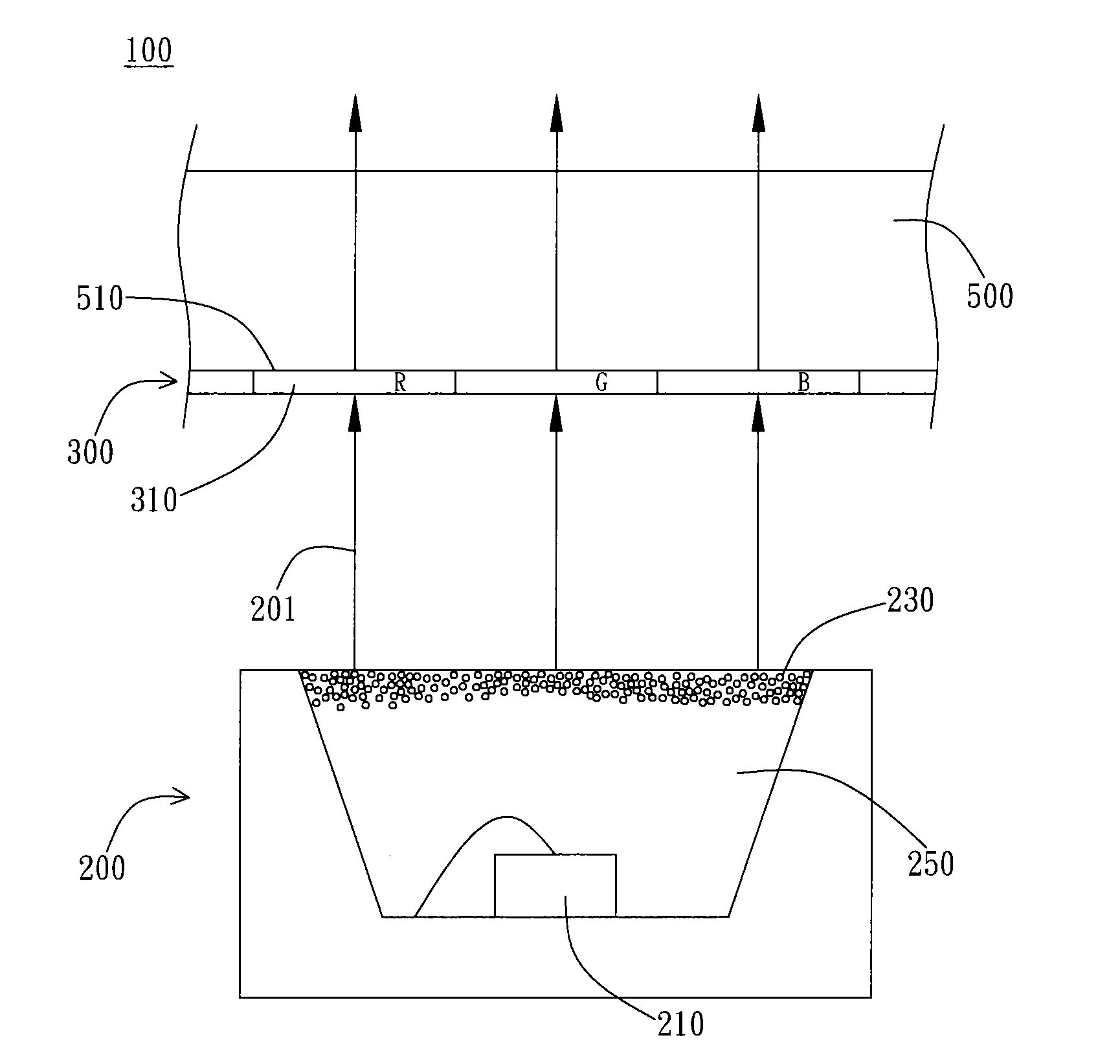
[0011]The color filter is disposed in a light path of the illumination unit to filter the color light generated by the illumination module. A transmittance spectrum of the color filter has a second blue peak, a second green peak, and a second red peak, and at each peak value each peak has a respective wavelength, including a second blue peak wavelength, a second green peak wavelength, and a second red peak wavelength. The first blue peak wavelength, the first green peak wavelength, and the first red peak wavelength respectively match with the second blue peak wavelength, the second green peak wavelength, and the second red peak wavelength to elevate the color performance of the display device.

Problems solved by technology

However the phosphors cannot be excited by blue light and cannot be used in white LED using blue exciting light.
When LED is used as a light source, because conventional phosphor have a greater full width at half maximum (FWHM), the color saturation will be lower and the color of images often is not satisfying.
Therefore, a light corresponding to the green peak 13 may pass through the blue color resist or the red color resist, which further results in color impurity.

Method used


Image

  • Display Device with Quantum Dot Phosphor and Manufacturing Method Thereof
  • Display Device with Quantum Dot Phosphor and Manufacturing Method Thereof
  • Display Device with Quantum Dot Phosphor and Manufacturing Method Thereof

Examples


Embodiment Construction

[0022]The present invention provides a display device and a manufacturing method thereof. In a preferred embodiment, the display device of the present invention is disposed within a display device to provide a light source for image generation. A display device preferably includes a liquid crystal display (LCD), such as a home LCD TV, LCD monitors for PC and laptop computer, and liquid crystal display panels of mobile phone and digital camera.

[0023]As FIG. 2 shows, a display device 100 includes an illumination unit 200 and a color filter 300. The color filter is disposed in a light path of the illumination unit, for filtering a color light generated by the illumination unit 200. The color filter 300 is preferably disposed on the side (or the opposite side) of an incident plane 510 of the display panel to filter the light entering the display panel 500, which can be LCD or other planar display panels. In the embodiment shown in FIG. 2, the illumination unit 200 is a light-emitting di...


PUM


Abstract

A display device and a method of manufacturing the same are provided. The display device includes an illuminate unit and a color filter. The illuminate unit has a light-emitting chip and a plurality of quantum dot phosphors for generating a color light which has an optical spectrum including the first blue peak wavelength, a first green peak wavelength, and a first red peak wavelength. The color filter is disposed in the light path of the color light, wherein the color filter has a transmittance spectrum having a second blue peak wavelength, a second green peak wavelength, and a second red peak wavelength. The first blue peak wavelength, the first green peak wavelength, and the first red peak wavelength respectively match the second blue peak wavelength, the second green peak wavelength, and the second red peak wavelength in order to enhance the color performance of the display device.

Description

BACKGROUND OF THE INVENTION[0001]1. Field of the Invention[0002]The present invention generally relates to a display device and a manufacture method thereof. Particularly, the present invention relates to a display device using quantum dot phosphor and a manufacture method thereof.[0003]2. Description of the Prior Art[0004]The Liquid Crystal Display (LCD) device is mainly composed of a liquid crystal panel and a backlight module. The liquid crystal does not illuminate, therefore it needs a backlight module to generate light, which is controlled by the molecules of the liquid crystal of the liquid crystal panel to produce images. For good color performance of the generated images, the collocation of the light generated by the backlight module and the color filter at the front side of the liquid crystal panel has become an important research topic.[0005]The light sources extensively used in a backlight module in the industrial circle are mainly cold cathode fluorescent lamp (CCFL) and...

Claims


Application Information

Patent Timeline
Patent Type & Authority Applications(United States)
IPC IPC(8): H01J1/62F23Q23/00B82Y30/00
CPCB82Y20/00B82Y30/00G02F1/133603C09K11/883G02F1/133514C09K11/565
Inventor YU, YI-CHENGWANG, CHIH-LINLIU, RU-SHILIN, CHUN-CHE
Owner AU OPTRONICS CORP
Learn More