Heat lamp

Inactive Publication Date: 2011-06-30
SIMKA PAVEL
View PDF5 Cites 20 Cited by
  • Summary
  • Abstract
  • Description
  • Claims
  • Application Information

AI Technical Summary

Benefits of technology

[0030]Into the device of the present invention is possible also to build a suitable storage of thermal energy. Such heat energy storage is usable to ensure the operation of thermoelectric generator in a shorter period, when the heat source has been disconnected. The heat energy is then pumped from the heat energy accumulator for example by the way of heat pumping using refrigerant or other suitable fluid through the use of phenomena such as evaporation and condensation, which occur by the collecting and delivering of heat energies. The heat pumping can be also solved on the principles of heat pipes and thermosiphons. Custom accumulator of heat energy is made up of a substance that has good thermal conductivity and good thermal absorption and consequently also a good release of stored heat energy.
[0033]From the perspective of the future are also important light foils which have minimal power consumption and good intensity. They will be well integrated into and / or onto different surfaces of various things.

Problems solved by technology

Too much heat can lead to state, when the wire gives the light.

Method used


Image

  • Heat lamp
  • Heat lamp
  • Heat lamp

Examples


example 1

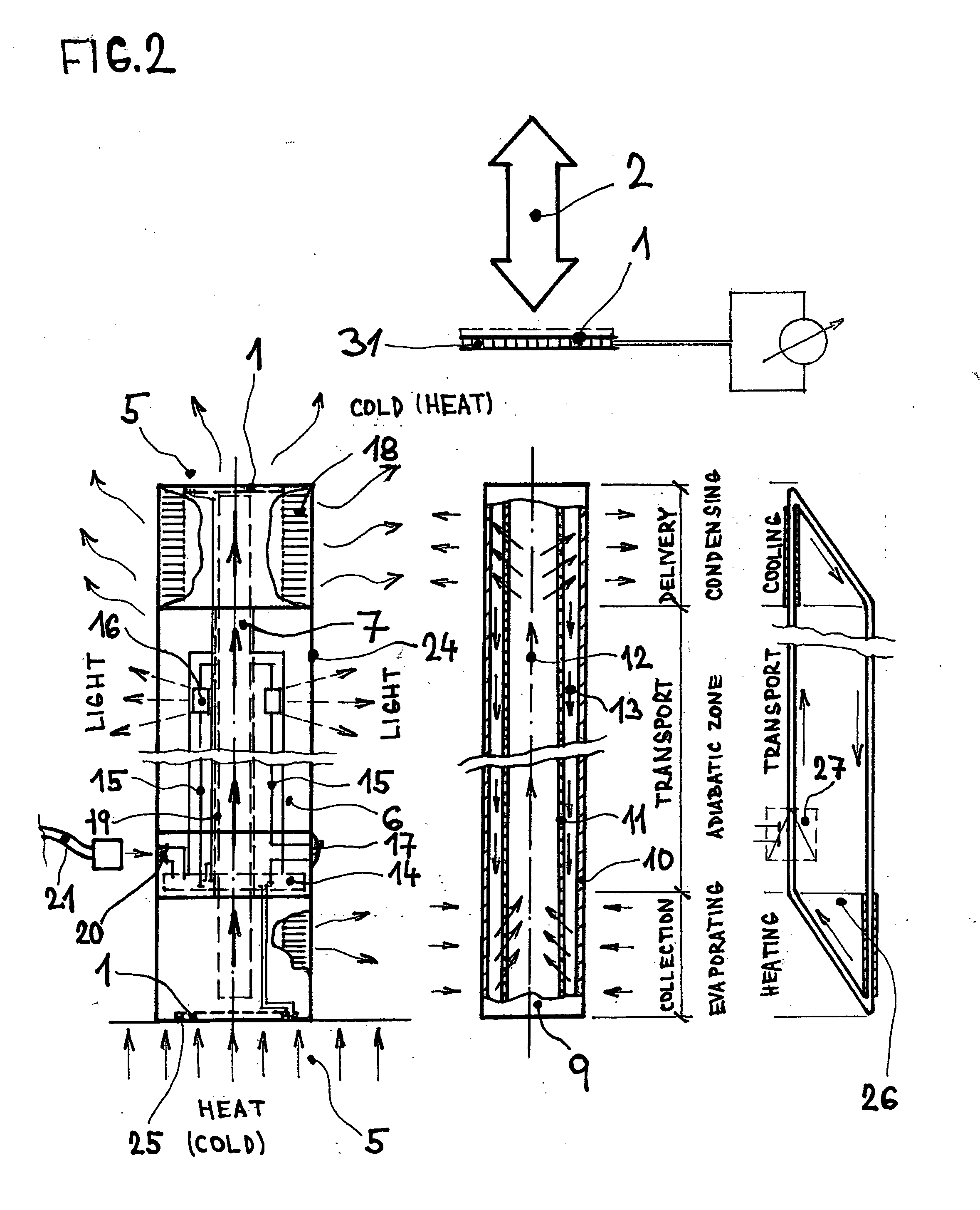
[0041]Device 6, as shown in FIG. 2 consists of at least one thermoelectric element 1, which is located on the device, here at the bottom part and / or on the top of device and at least one thermoelectric element is in contact with heated or with cooled surface as a source of heat and / or cold 5. Characteristic for this construction is that part of such device 6 is with at least one thermal conductor 7, which provides efficient heat dissipation from the surface of thermoelectric element 1, and from the side which is not in direct contact with the heat source 5, and the side is in optimal construction isolated from its effects. At least one thermoelectric element 1 is placed in such a way, that the area which is in heat contact with the heat source is not in contact with the other side of the element, which is in heat exchange contact with a conductor and / or cooler for heat dissipation. Thermal partition 25 can be made from heat insulating material and / or is solved as a slit. An appropri...

example 2

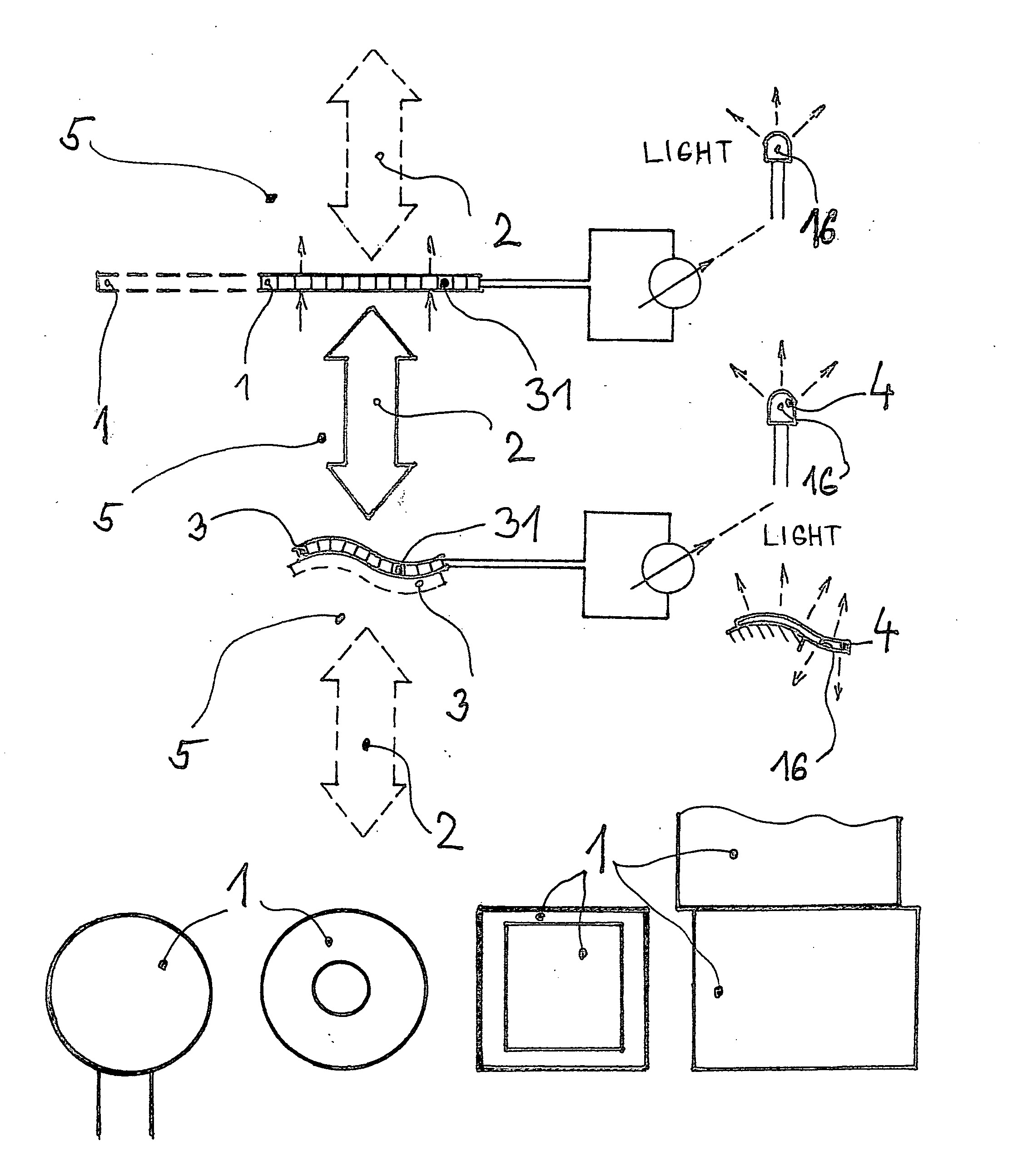
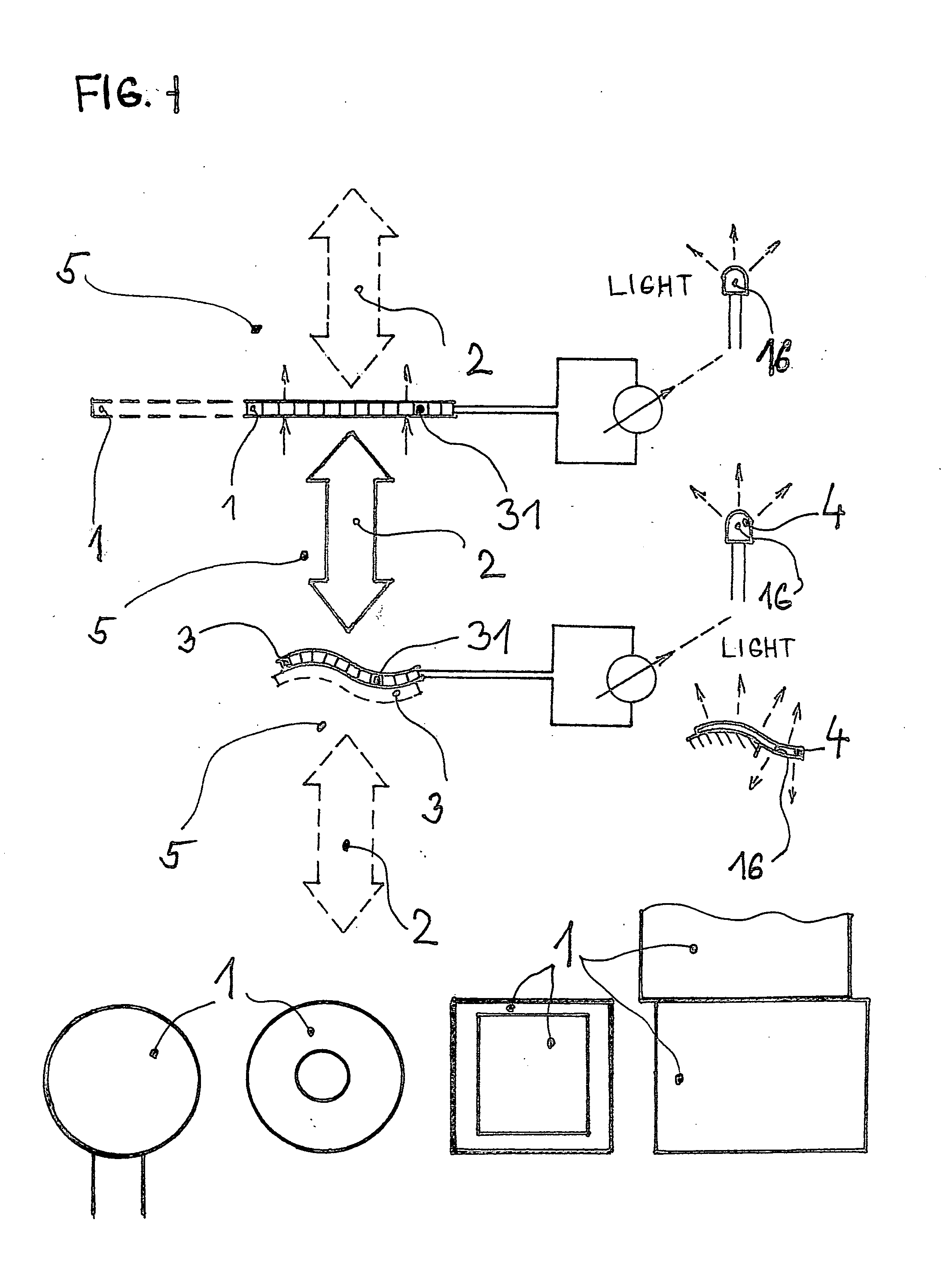
[0045]The device 8, as shown in FIG. 3 consists of at least one thermoelectric element 1, which is located on the device 8, here at the bottom part, which is in contact with heated and / or with cooled surface of source of heat 5 and / or source of cold 5. Characteristic for this construction is that part of such device 8 is without thermal conductor 7, as in the device 6 in FIG. 2. Heat dissipation from the other side of the thermoelectric element 1 is realized by conduction to material of the cooler 18, from which is heat transferred mainly by radiation to the surroundings. An active heat dissipation can be realized also by using a minimotor and a propeller. The insulated location of thermoelectric element 1 is solved again with slot 25 and / or with a heat-insulating material. The device is equipped with at least one thermoelectric element 1, which is connected to the controller charge / discharge 14, that is electrically connected to the battery(ies) 22. Furthermore, the regulator of ch...

example 3

[0046]The device 8, as shown in FIG. 3, in another embodiment can be implemented as a device with thermosiphon, which is directly formed at least partially with a transparent tube 24 and partially with heat conductive case. Implementation of the tube 24 is sufficiently long in relation to its diameter and to function of thermosiphon. Inside the compartment 23 is directly circulated a heat transfer medium through evaporation and condensation, medium for example such as refrigerant. Before filling the compartment inside, the device is evacuated. Heat dissipation works similarly to the internal model with thermosiphon in FIG. 2. At the bottom part of device is the evaporation of fluid and in the top part of device is condensation of fluid.


PUM


Abstract

Device for the production of light contains at least one thermoelectric element, which is in thermal communication with a source of thermal energy, the electricity for production of light is generated by thermal effects on the surfaces of element through heat pumping, and the transformation of thermal energy into electrical energy is realized and electricity is produced in at least one thermoelectric cell, produced current is led into the controller of charge and / or discharge, and / or into at least one accumulator, and the regulator of charge and / or discharge is connected through power lines on at least one lighting element, which provides conversion of electric energy to light and is connected with at least one switch and leads into the regulator charge and / or discharge, and characteristic is that, the electrical current leads through at least one lighting element, the device transmits light energy and the light is on.

Description

TECHNICAL FIELD[0001]The technical solution relates to the use of thermal energy of one or more substances or materials for thermoelectric electricity generation using at least one thermoelectric cell or element and its subsequent use for manufacture of light and / or to power other electrical appliances.[0002]Heat energy and temperature differences usable for power generation and especially for production of light presented in this invention occur generally thanks to an energetic action, either is natural or we can say is artificially induced, for example from human activities.[0003]In the case of the natural thermal energy it is mainly on the use of direct sunlight or thermal energy stored from the sun or from the earth's core into air, water, soil and various substances, things and objects which are exposed to effect of such thermal energy.[0004]The induced thermal energy are also generated in system operations of various devices, machinery and equipment, in which is simply generat...

Claims


Application Information

Patent Timeline
Patent Type & Authority Applications(United States)
IPC IPC(8): H01L35/30H10N10/13H10N10/01
CPCH01L35/30H10N10/13
Inventor SIMKA, PAVEL
Owner SIMKA PAVEL
Why Eureka
Try Eureka