Gas pressure monitoring system and gas-insulated electric apparatus

Inactive Publication Date: 2011-06-23
MITSUBISHI ELECTRIC CORP
View PDF0 Cites 20 Cited by
  • Summary
  • Abstract
  • Description
  • Claims
  • Application Information

AI Technical Summary

Benefits of technology

[0008]According to a gas pressure monitoring system configured as described above, the system calculates a slope of a characteristic curve expressing a relationship between pressure and temperature for each of predetermined periods, so that the system can precisely detect changes in charging pressure of the gas enclosed in the hermetic container, enabling early detection of gas leakage in a gas-insulated electric apparatus.

Problems solved by technology

Therefore, the equivalent pressure calculated from the temperature and the pressure measured by the temperature sensor and the pressure sensor both provided at arbitrary portions of the gas pressure monitoring system also fluctuates, and it is difficult to compensate the fluctuation, causing a difficulty in recognizing gas leakage or the like.
However, the equivalent pressure obtained, as described above, from the temperature and the pressure at a predetermined time largely varies over days, having a problem in its accuracy.
Thus, this cannot provide early detection of gas leakage.

Method used


Image

  • Gas pressure monitoring system and gas-insulated electric apparatus
  • Gas pressure monitoring system and gas-insulated electric apparatus
  • Gas pressure monitoring system and gas-insulated electric apparatus

Examples


embodiment 1

[0019]Embodiment 1 according to the present invention will be explained in detail below, using figures.

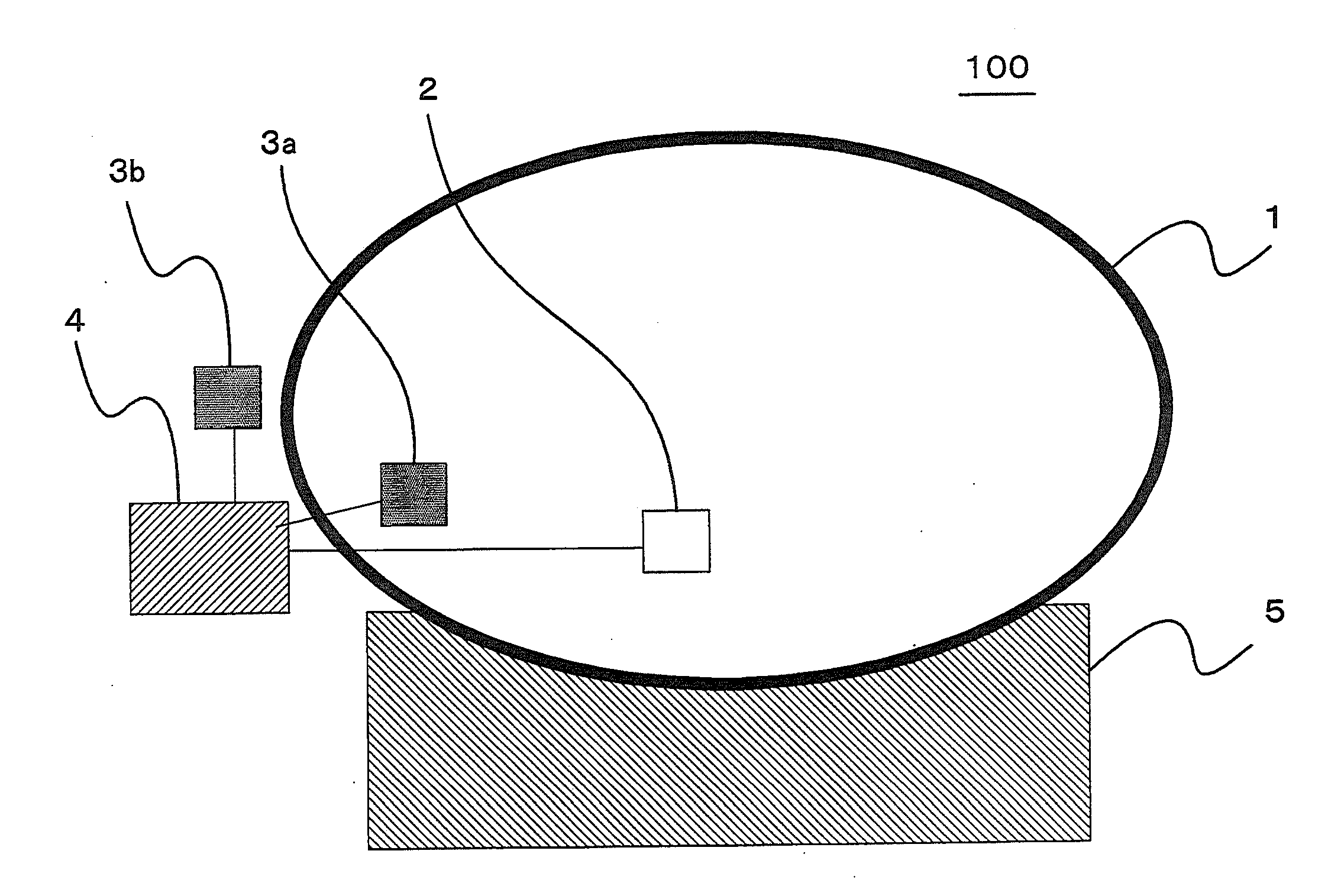
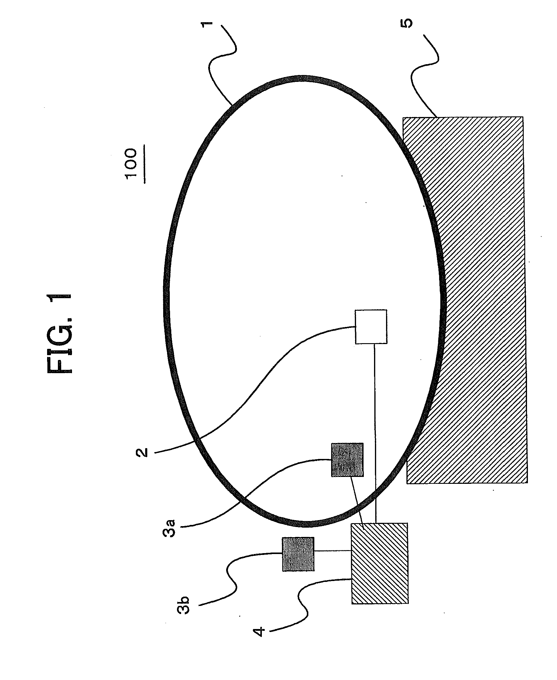
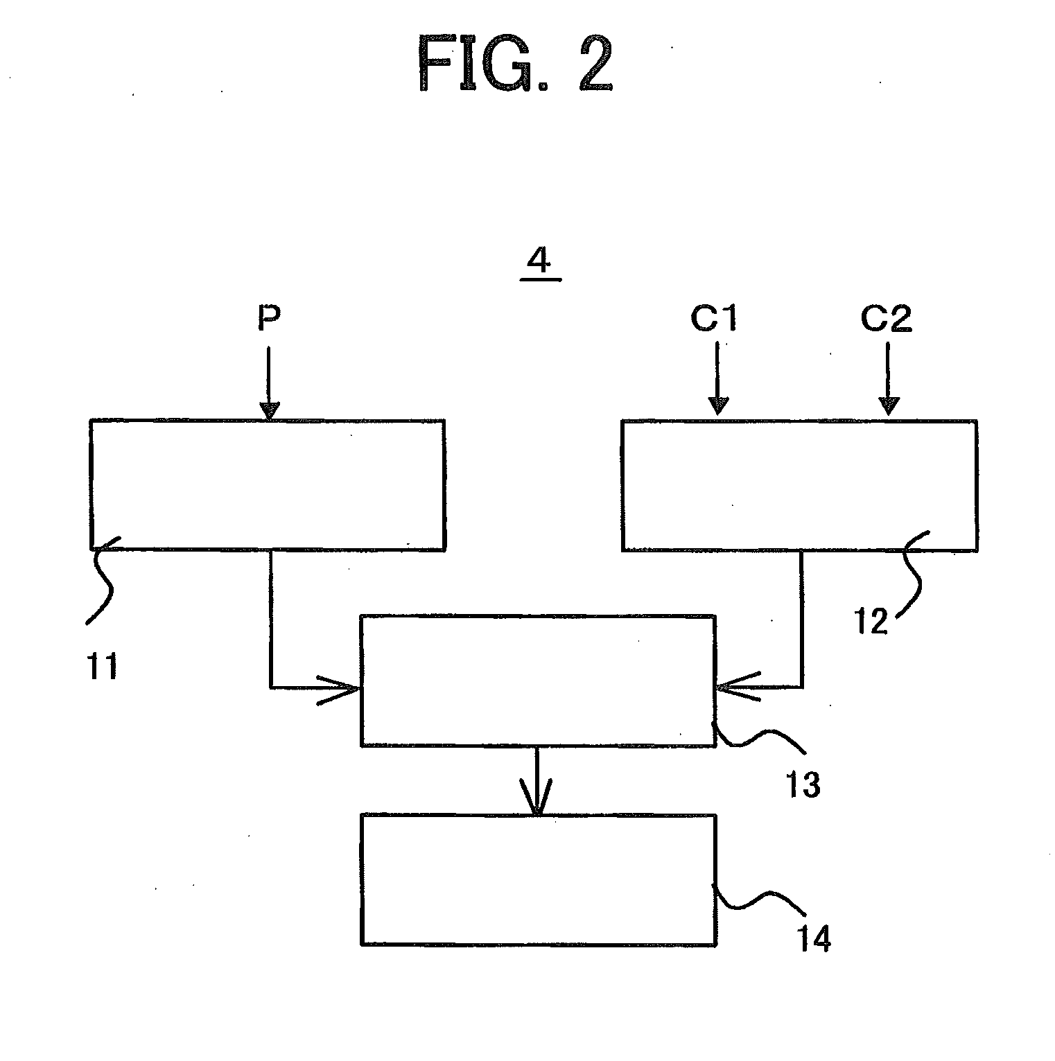
[0020]FIG. 1 is a configurational diagram of a gas-insulated electric apparatus provided with a gas pressure monitoring system according to Embodiment 1 of the present invention; FIG. 2 is a block diagram of an arithmetic processing apparatus provided in the gas pressure monitoring system; FIG. 3 is a graph that shows characteristic curves each of which corresponds to the charging pressure (a pressure in a container at a predetermined temperature) of an SF6 gas enclosed in the gas pressure monitoring system; FIG. 4 a correlation diagram between the charging pressure of the SF6 gas at 20° C. and slopes of the characteristic curves mentioned above; FIG. 5 is a graph that shows temporal change of temperature measurements sensed by temperature sensors of the gas pressure monitoring system; FIG. 6 is a graph that shows a characteristic curve sensed by a first temperature sensor; FIG. 7 ...


PUM


Abstract

In a conventional gas pressure monitoring system that detects a gas leak inside the hermetic container using temperatures measured by the temperature sensor provided outside the hermetic container, there exist uncertain temperature differences between actual temperatures inside the hermetic container and measured temperatures. Thus it is difficult to obtain from a pressure measured inside the hermetic container, an equivalent pressure converted to one at a predetermined temperature, so that it is not possible to early detect a gas leak. By removing the influence of the uncertain differences between temperatures inside and outside the hermetic container, from characteristic-curve slopes obtained from time-series measurements in pressure and temperature during predetermined periods at intervals of 24 hours, it becomes possible to obtain an equivalent pressure inside the hermetic container with a high accuracy, to detect a gas leak at early stages.

Description

TECHNICAL FIELD[0001]The present invention relates to a gas pressure monitoring system that monitors a leak of gas enclosed in a gas-insulated electric apparatus such as a gas-insulated switchgear and relates to a gas-insulated electric apparatus provided therewith.BACKGROUND ART[0002]In a conventional gas pressure monitoring system, a gas pressure sensor and a temperature sensor are provided in a hermetic container of a gas-insulated electric apparatus, and the pressure and temperature measured by the sensors are used to calculate an equivalent pressure corresponding to a temperature determined in advance, using the gas state equation or Beattie-Bridgeman equation, and change in the equivalent pressure is monitored to recognize gas leakage of the gas-insulated electric apparatus (for example, refer to Patent document 1: Japanese Patent Laid-Open No. 1986(S61)-227327).[0003]The temperature in the hermetic container provided for the gas-insulated electric apparatus depends on changes...

Claims


Application Information

Patent Timeline
IPC IPC(8): G01M3/16
CPCG01M3/002H02B13/065G01M3/32H02B13/0655
Inventor ITO, TAKASHI
Owner MITSUBISHI ELECTRIC CORP
Why Eureka
Try Eureka