
Discrete time receiver

Inactive Publication Date: 2011-06-23
ELECTRONICS & TELECOMM RES INST
View PDF11 Cites 10 Cited by
  • Summary
  • Abstract
  • Description
  • Claims
  • Application Information

AI Technical Summary

Benefits of technology

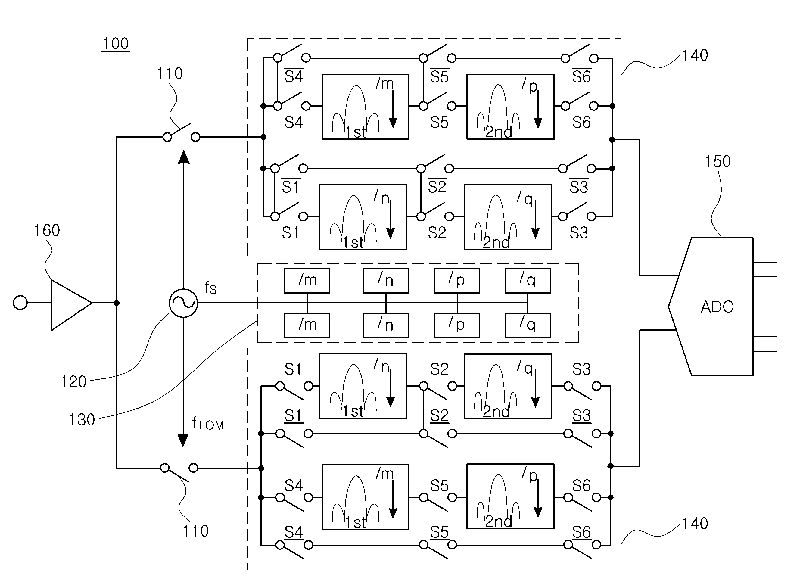
[0021]An aspect of the present invention provides a discrete-time receiver capable of performing sampling in an RF area and enabling an analog-to-digital converter (ADC) to have high resolution by adjusting a decimation rate according to a sampling frequency to lower the frequency of an output signal so as to become a sampling frequency of the ADC.

Problems solved by technology

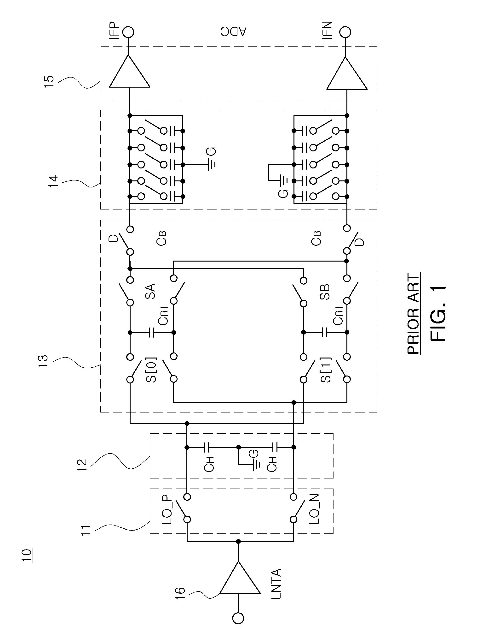
However, the recent discrete-time receiver has a narrow operation band, so its application is therefore limited.
Referring to the structure of the discrete-time receiver, an element such as an SDR (Software Defined Radio) supports a broad band operation (or a wide band operation), causing no problem in processing a broadband signal, but an ADC, a core element of the discrete-time receiver, cannot sufficiently support the broad band in the operation speed, conversion performance, and the like thereof.
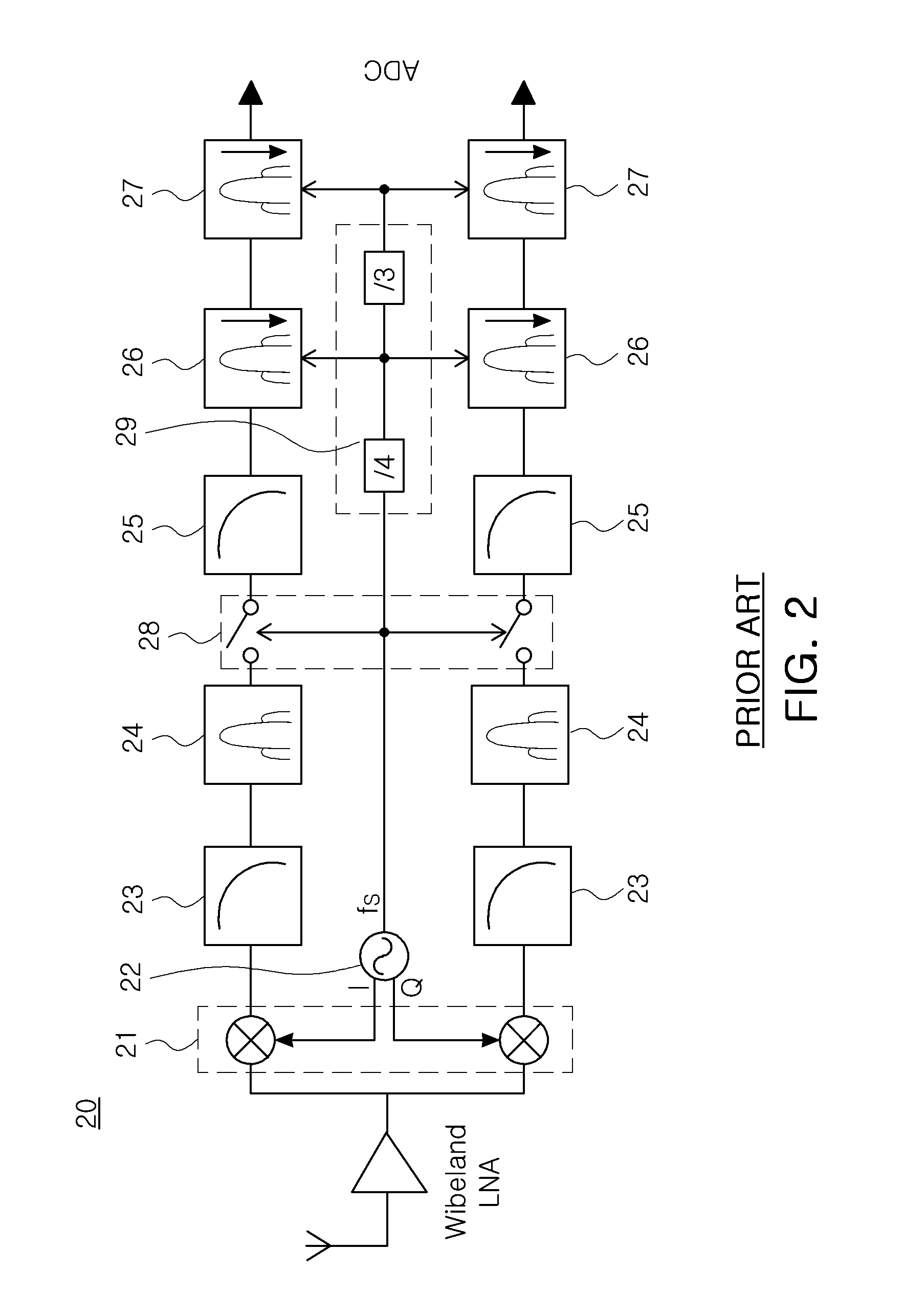
In terms of the overall performance and circuit design, the RF receiver 20 illustrated in FIG. 2, except for the decimation filters 26 and 27, has superior performance to the discrete-time receiver 10 of FIG. 1, but is disadvantageous in that its structure is almost similar to the existing analog structure and main blocks are used.

Method used


Image

  • Discrete time receiver
  • Discrete time receiver
  • Discrete time receiver

Examples


Embodiment Construction

[0032]Exemplary embodiments of the present invention will now be described in detail with reference to the accompanying drawings. The invention may, however, be embodied in many different forms and should not be construed as being limited to the embodiments set forth herein. Rather, these embodiments are provided so that this disclosure will be thorough and complete, and will fully convey the scope of the invention to those skilled in the art.

[0033]In the drawings, the shapes and dimensions may be exaggerated for clarity, and the same reference numerals will be used throughout to designate the same or like components.

[0034]Unless explicitly described to the contrary, the word “comprise” and variations such as “comprises” or “comprising,” will be understood to imply the inclusion of stated elements but not the exclusion of any other elements.

[0035]A discrete-time receiver according to an exemplary embodiment of the present invention proposes a receiver structure that can be used in v...


PUM


Abstract

A discrete-time receiver includes: a sampling mixer sampling an input signal according to a sampling clock; a discrete-time filter adjusting a decimation rate by using a control signal and filtering the sampled signal by using a filter clock; and a clock generator generating a sampling clock to be supplied to the sampling mixer, and generating the control signal and the filter clock by comparing the frequency of the sampling clock with a pre-set output frequency. Over a broadband input signal, a dynamic range of an output signal can be improved.

Description

CROSS-REFERENCE TO RELATED APPLICATIONS[0001]This application claims the priority of Korean Patent Application Nos. 10-2009-0127534 filed on Dec. 18, 2009 and 10-2010-0115079 filed on Nov. 18, 2010, in the Korean Intellectual Property Office, the disclosures of which are incorporated herein by reference.BACKGROUND OF THE INVENTION[0002]1. Field of the Invention[0003]The present invention relates to an RF discrete-time receiver covering a broad band (or a wide band).[0004]2. Description of the Related Art[0005]Conventionally, an analog-type continuous-time receiver has been widely used, and recently, a discrete-time receiver has been developed to be applied to a plurality of products. However, the recent discrete-time receiver has a narrow operation band, so its application is therefore limited.[0006]Referring to the structure of the discrete-time receiver, an element such as an SDR (Software Defined Radio) supports a broad band operation (or a wide band operation), causing no proble...

Claims


Application Information

Patent Timeline
IPC IPC(8): H03K9/00H04L25/10
CPCH04B1/005H04B1/0003
Inventor LEE, YOUNG JAE
Owner ELECTRONICS & TELECOMM RES INST
Learn More