Voltage controlled oscillator
a voltage control and oscillator technology, applied in the direction of oscillator, pulse generator, pulse technique, etc., can solve the problems of insufficient magnitude of generated signals, degraded oscillator performance, and increased occupied area and power consumption, and achieve the effect of extending the structur
- Summary
- Abstract
- Description
- Claims
- Application Information
AI Technical Summary
Problems solved by technology
Method used
Image
Examples
first embodiment
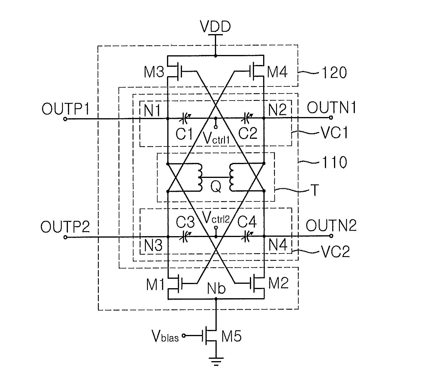
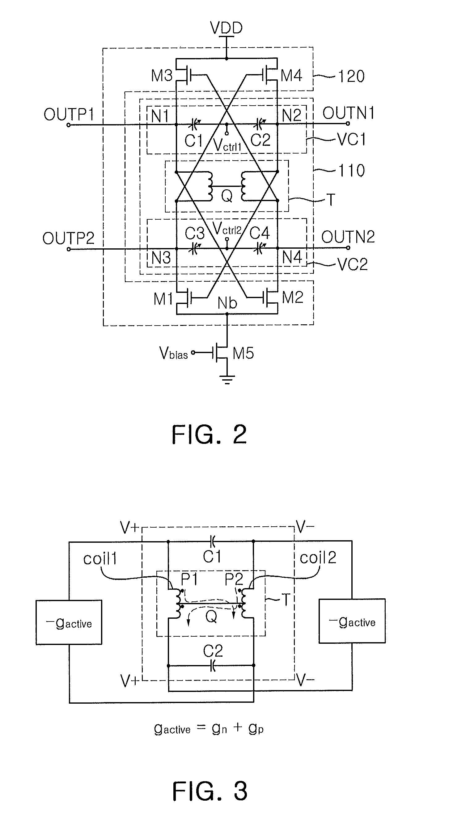
[0042]FIG. 2 is a diagram illustrating a voltage controlled oscillator according to the present invention.
[0043]Referring to FIG. 2, the voltage controlled oscillator according to the first embodiment of the present invention includes a resonant circuit 110 and a negative resistance circuit 120. The resonant circuit 110 includes one transformer T and two variable capacitor circuits VC1 and VC2 connected in parallel to the transformer T, and generates four oscillation frequencies to output to four oscillation nodes N1 to N4. The negative resistance circuit 120 includes four transistors M1 to M4 cross-coupled via the transformer T, and generates negative resistance for maintaining the oscillation of the resonant circuit 110. The voltage controlled oscillator configured in such a manner oscillates at four oscillation frequencies.
[0044]The connection relationship between the respective components will be described in more detail as follows.
[0045]The transformer T includes a primary coil...
second embodiment
[0060]FIG. 5 is a conceptual diagram of a voltage controlled oscillator according to the present invention.
[0061]Referring to FIG. 5, the voltage controlled oscillator according to the second embodiment of the present invention may include a plurality of transformers T connected in parallel so as to increase the number of oscillation nodes.
[0062]When n oscillation phases (where n is a multiple of 2 which is equal to or greater than 6) are to be obtained, (n / 2−1) transformers T and (n / 2) varactor diodes C are required. The phase of each oscillation node of the voltage controlled oscillator configured in such a manner becomes 2p / n.
[0063]That is, according to the second embodiment of the present invention, the transformers T and the varactor diodes C may be connected to form multi-phase oscillation nodes P1, P2, . . . , Pn, in order to obtain a desired number of phases.
[0064]FIG. 6 is a diagram illustrating the voltage controlled oscillator according to the second embodiment of the pre...
third embodiment
[0076]FIG. 8 is a diagram illustrating a voltage controlled oscillator according to the present invention.
[0077]Referring to FIG. 8, the voltage controlled oscillator 300 according to the third embodiment of the present invention includes a resonant circuit 310 configured in a similar manner to the resonant circuit of FIG. 5. However, the resonant circuit 310 includes transformer T1 and T2 having a plurality of center taps and divided into a plurality of inductors L1 to L4. The respective inductors are connected through switches SW1 to SW3.
[0078]More specifically, after the first and second transformers T1 and T2 are divided into four inductors, the first inductor L1 inside the same transformer and between different transformers may be connected through the first switch SW1, the second inductor L2 may be connected through the second switch SW2, and the third inductor L3 may be connected through the third switch SW3. In this case, only the first switch SW1 may be turned on to operate...
PUM
 Abstract
Description
Claims
Application Information
 - R&D
- Intellectual Property
- Life Sciences
- Materials
- Tech Scout
- Unparalleled Data Quality
- Higher Quality Content
- 60% Fewer Hallucinations
Browse by: Latest US Patents, China's latest patents, Technical Efficacy Thesaurus, Application Domain, Technology Topic, Popular Technical Reports.
© 2025 PatSnap. All rights reserved.Legal|Privacy policy|Modern Slavery Act Transparency Statement|Sitemap|About US| Contact US: help@patsnap.com


