
Polygonal laser scanner for coating removal

a polygonal laser and coating technology, applied in the field of laser systems and devices, can solve the problems of power handling capability (6 kw) and weight (>60 lbs) limitations of currently available oscillatory scanners, and achieve the effect of reducing the cost of operation and maintenance, improving the scanning efficiency, and improving the scanning efficiency

Active Publication Date: 2011-06-23
XYREC IP BV
View PDF9 Cites 5 Cited by
  • Summary
  • Abstract
  • Description
  • Claims
  • Application Information

AI Technical Summary

Problems solved by technology

Some success has been achieved with galvanometer-based oscillatory scanning mirrors; however, these scans are limited in surface scan speed to typically less than 10 m / s and suffer from dead zones at the end of the scan where the mirror decelerates, reverses, and reaccelerates.
Other limitations of currently available oscillatory scanners are power handling capability (60 lbs).

Method used


Image

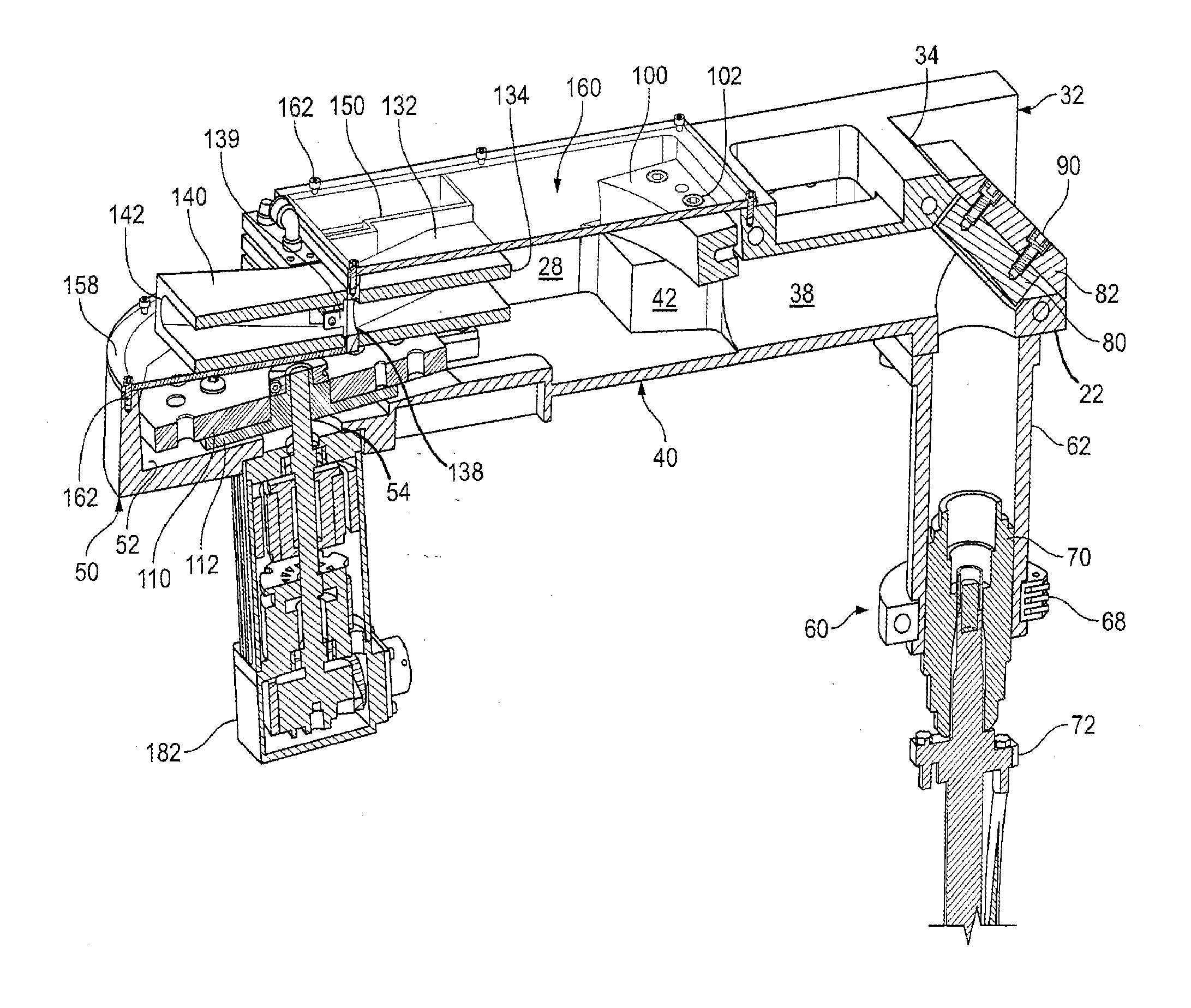
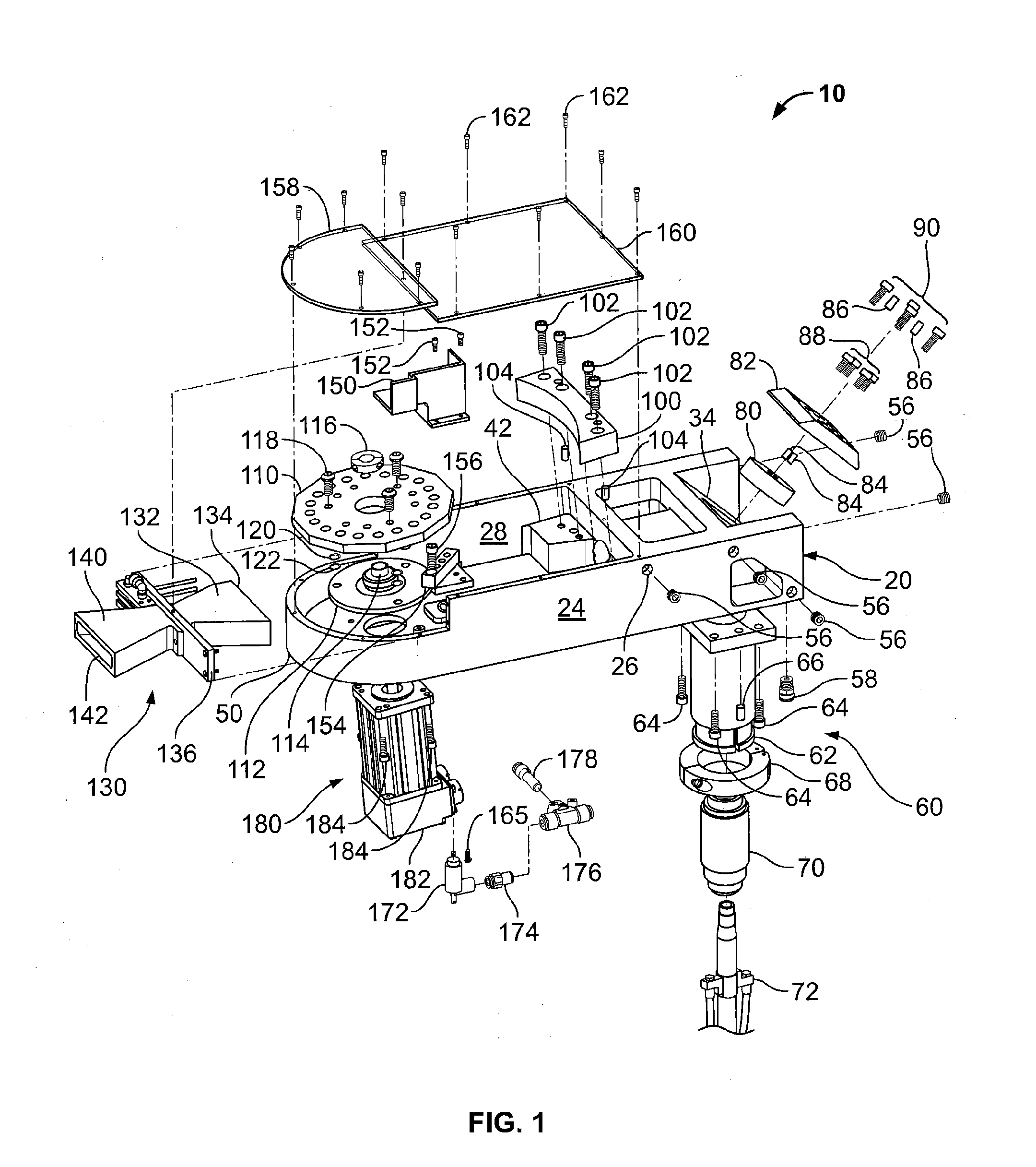
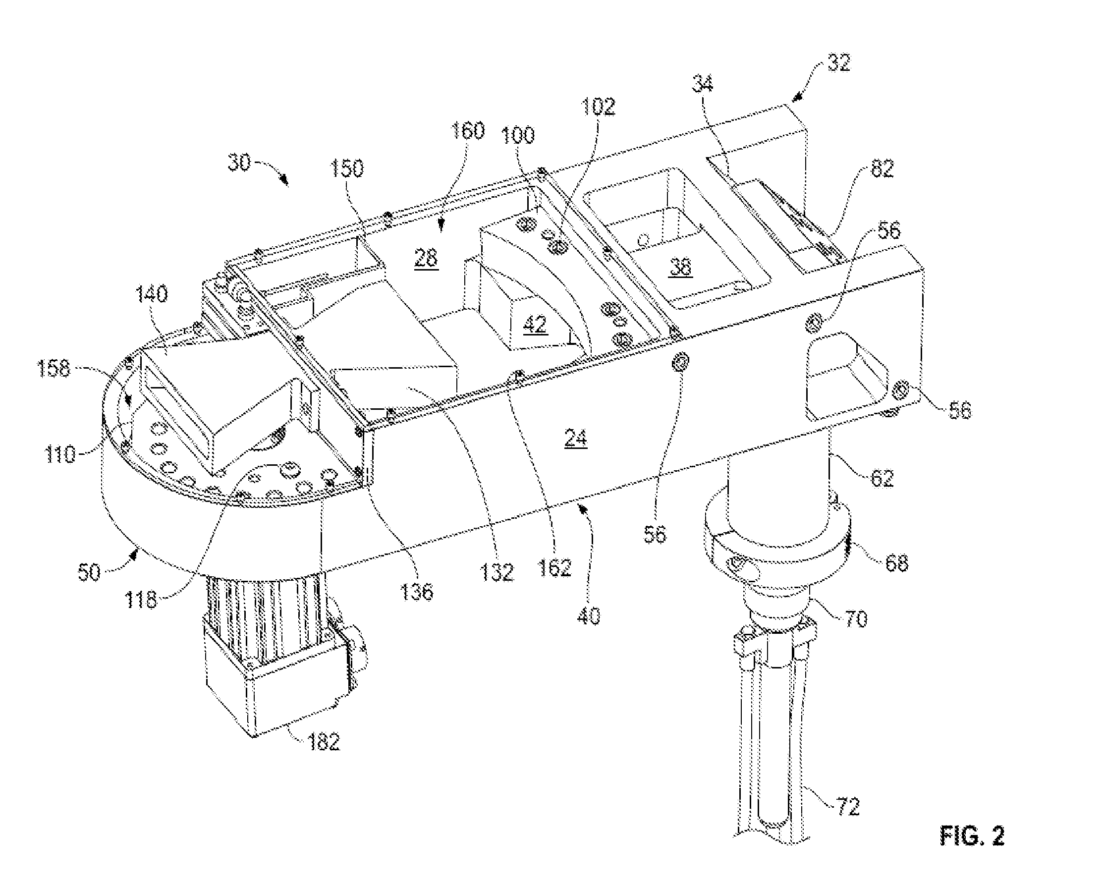
  • Polygonal laser scanner for coating removal
  • Polygonal laser scanner for coating removal
  • Polygonal laser scanner for coating removal

Examples


Embodiment Construction

[0020]Exemplary embodiments of the present invention are now described with reference to the Figures. Reference numerals are used throughout the detailed description to refer to the various elements and structures. Although the following detailed description contains many specifics for the purposes of illustration, a person of ordinary skill in the art will appreciate that many variations and alterations to the following details are within the scope of the invention. Accordingly, the following embodiments of the invention are set forth without any loss of generality to, and without imposing limitations upon, the claimed invention. The present invention relates to a system for removing materials such as paint and other coatings from various surfaces, wherein the system includes a laser scanner having multiple optics. With reference now to the Figures, one or more specific embodiments of this invention shall be described in greater detail.

[0021]As best shown in FIGS. 1-6, an exemplary...


PUM

PropertyMeasurementUnit
thicknessaaaaaaaaaa
surface scan speedaaaaaaaaaa
weightaaaaaaaaaa

Abstract

A laser scanner system for removing a coating from a surface. The system includes a laser source for generating a laser beam; a focusing optic operative to receive, focus and re-direct the laser beam; a rotating multi-faceted mirror for receiving and reflecting the focused laser beam, wherein the rotating multi-faceted mirror repeatedly translates the reflected focused laser beam in one direction along an arc path and through a first focal point, and wherein passage of the laser beam through the first focal point results in divergence of the beam; a reimaging mirror for receiving and reflecting the divergent laser beam toward a work surface, wherein the reimaging mirror produces an image of the first focal point and its path; and wherein the rotating multi-faceted mirror and the reimagining mirror cooperate to produce a beam cross-over region having a minimal cross-sectional area relative to other points along the beam path, and wherein the beam cross-over region is located between the reimaging mirror and the work surface.

Description

CROSS-REFERENCE TO RELATED APPLICATIONS[0001]This patent application claims the benefit of U.S. Provisional Patent Application Ser. No. 61 / 289,826 filed on Dec. 23, 2009 and entitled “Polygonal Laser Scanner for Coating Removal,” the disclosure of which is hereby incorporated by reference herein in its entirety and made part of the present U.S. utility patent application for all purposes.BACKGROUND OF THE INVENTION[0002]The present invention relates generally to systems and devices utilizing lasers, and more specifically to a system for removing materials such as paint and other coatings from various surfaces, wherein the system includes a laser scanner having multiple cooperative optics having unique characteristics.[0003]The application of laser technology for the removal of coatings developed several decades ago and small hand-held devices (100-500 W) are now available commercially for small area coating removal tasks. “Coating” typically refers to all types of unwanted surface m...

Claims


Application Information

Patent Timeline
Patent Type & Authority Applications(United States)
IPC IPC(8): B23K26/36G02B26/12
CPCB23K26/365G02B26/126B44D3/16B23K26/361
Inventor REAM, STANLEY L.WALTERS, CRAIG T.
Owner XYREC IP BV
Learn More