Method for producing a fuel tank

Inactive Publication Date: 2011-06-23
BENTELER DEFENSE
View PDF5 Cites 1 Cited by
  • Summary
  • Abstract
  • Description
  • Claims
  • Application Information

AI Technical Summary

Benefits of technology

[0013]The elastomer layer exhibits the characteristic to swell upon contact with the fuel. The elastomer layer made of the rubber mixture is homogenized during vulcanization. The long-chain rubber molecules are cross-linked by sulfur bridges under the influence of the temperature. With the method of the invention, overlaps and joints between the individual rubber layers are advantageously evened out by the vulcanization process, producing a homogeneous elastomer layer of substantially constant wall thickness. The method of the invention significantly improves the accuracy, in particular the dimensional accuracy, for repeated process cycles over non-vulcanized elastomer layers.
[0017]For improving fire protection, a gel coat based on a epoxy resin is used as a cover layer, which due to its higher ignition point extends the time during which the elastomer layer and hence the fuel tank is resistant to fire. The flame point of the gel coat and / or the cover layer is higher than the flame point of the elastomer layer.
[0021]With the method of the invention, a cover for fuel tanks resisting leakage can be produced with high reliability. This cover does not have any weak points caused by different material thicknesses due to overlaps and material joints and, in addition, has a uniform, precisely defined exterior geometry, preventing the fuel tank from colliding with adjacent components and structures during installation.

Problems solved by technology

These rubber compositions are typically applied as individual sections placed on the fuel tank, which produces overlaps and / or material joints that can cause variations in the material thickness and hence in the overall effectiveness.
This may disadvantageously cause irregularities on the exterior surface of such lined series-produced fuel tanks.
In other words, this manufacturing technique has a relatively low process reliability.
The manual manufacturing process causes unavoidable variations in the material thickness.

Method used


Image

  • Method for producing a fuel tank
  • Method for producing a fuel tank

Examples


Embodiment Construction

[0026]Throughout all the figures, same or corresponding elements may generally be indicated by same reference numerals. These depicted embodiments are to be understood as illustrative of the invention and not as limiting in any way. It should also be understood that the figures are not necessarily to scale and that the embodiments are sometimes illustrated by graphic symbols, phantom lines, diagrammatic representations and fragmentary views. In certain instances, details which are not necessary for an understanding of the present invention or which render other details difficult to perceive may have been omitted.

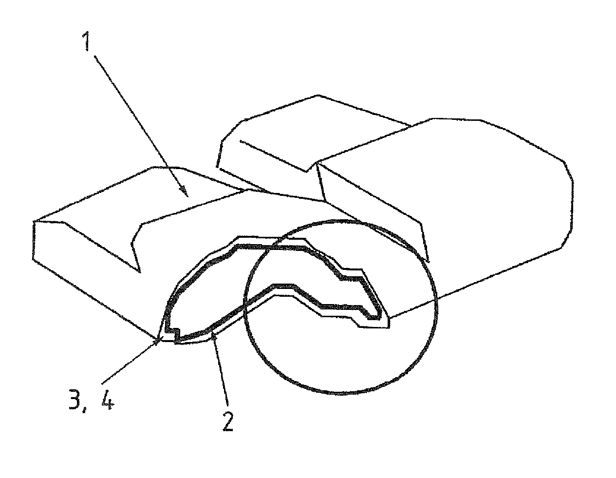
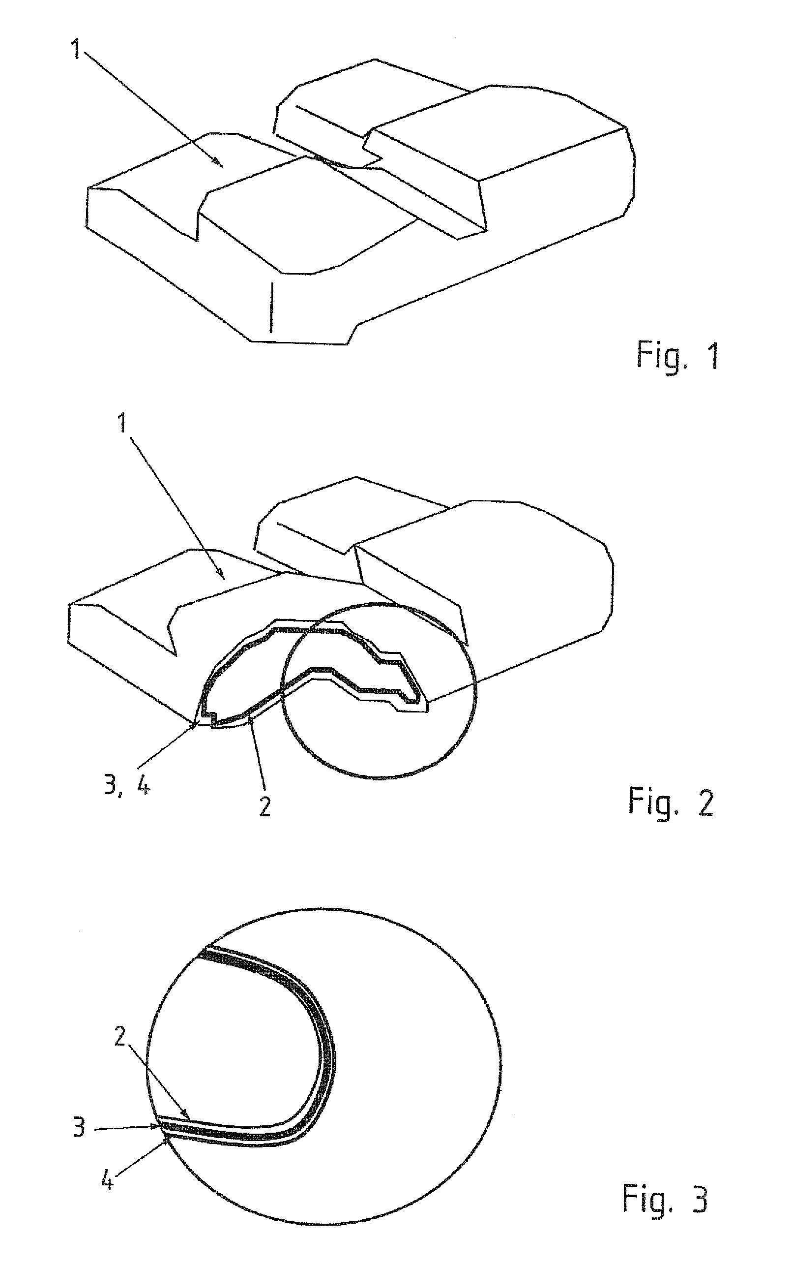
[0027]Turning now to the drawing, and in particular to FIG. 1, there is shown a fuel tank 1 of a type produced with the method of the invention as a final product. The fuel tank 1 has a complex configuration adapted to the respective vehicle geometry. The fuel tank 1 has a three-layer structure, as illustrated in FIGS. 2 and 3.

[0028]The fuel tank 1 includes initially an inte...


PUM

PropertyMeasurementUnit
Temperatureaaaaaaaaaa
Timeaaaaaaaaaa

Abstract

In a method for producing a fuel tank, an elastomer layer made of a rubber mixture is applied on an interior shell adapted to receive fuel, a fiber composite material forming a protective cover is introduced into a mold, inserting the fuel tank with the elastomer layer in the mold so as to surround the elastomer layer with the fiber composite material, the fiber composite material is adhesively bonded to the elastomer layer with a laminating resin, and the fuel tank with the protective cover is vulcanized at temperatures between 80° C. and 180° C. over a time of 2 hours to 36 hours. The fiber composite material includes a cover layer made of a gel coat having a higher flame point than the elastomer layer.

Description

CROSS-REFERENCES TO RELATED APPLICATIONS[0001]This application claims the priority of German Patent Application, Serial No. 10 2009 030 221.2, filed Jun. 23, 2009, pursuant to 35 U.S.C. 119(a)-(d), the content of which is incorporated herein by reference in its entirety as if fully set forth herein.BACKGROUND OF THE INVENTION[0002]The invention relates to a method for producing a fuel tank for vehicles, in particular motor vehicles.[0003]The following discussion of related art is provided to assist the reader in understanding the advantages of the invention, and is not to be construed as an admission that this related art is prior art to this invention.[0004]It is known to provide fuel tanks used in motor vehicles with jackets that hinder fuel leakage. Such jackets ensure that as little fuel as possible is discharged from the fuel tank after ballistic impact of a projectile or fragments, in order to prevent ignition of the vehicle underbody caused by incendiaries or other ignition s...

Claims


Application Information

Patent Timeline
IPC IPC(8): B29C65/72B29C65/52
CPCB29C35/02B60K2015/03407B60K2015/03046B60K15/03177
Inventor BORCHERT, ULRICHSKOWRONEK, JENS
Owner BENTELER DEFENSE
Why Eureka
Try Eureka