Impeller Installation Tool

a technology for installing tools and impellers, which is applied in the direction of manufacturing tools, machines/engines, liquid fuel engines, etc., can solve the problems of difficult installation, difficult task, and extremely limited both view of the water pump and access thereto, and achieve the effect of facilitating the installation of flexible impellers

Active Publication Date: 2011-06-23
PECHERZEWSKI ANDRZEJ
View PDF10 Cites 12 Cited by
  • Summary
  • Abstract
  • Description
  • Claims
  • Application Information

AI Technical Summary

Benefits of technology

[0004]The impeller is loaded onto the tool by pressing a plurality of the impeller blades against the inclined impeller engaging surface in the upper end of the tool while concurrently rotating the impeller in the direction of the rotation of the water pump shaft onto which it is to be mounted and urging the impeller downwardly into the tool, causing uniform rearward deformation of the impeller blades about the central impeller axis. The impeller is then pressed to the lower portion of the tool in its compressed state. With the impeller so loaded in the tool in a substantially uniformly deformed state, the tool is inserted into the impeller cavity in the water pump in axial alignment with the water pump shaft and rotated with respect thereto until the keying feature on the impeller hub is brought into axial alignment with the corresponding keying feature on the pump shaft. The impeller is then pushed downwardly within the tool about and along the shaft to the bottom of the impeller cavity. The tool is then pulled upwardly from the cavity as it is again rotated in the direction of rotation of the shaft on which it is mounted. The friction between the engaged impeller hub and pump shaft will maintain the impeller in place on the shaft as the tool is removed from the impeller cavity, leaving the impeller properly positioned on the pump shaft within the impeller cavity such that the uniformly deformed blades bear outwardly against the impeller cavity wall.
[0005]It is the principle object of the present invention to provide a tool for facilitating the installation of a flexible impeller in a water pump.

Problems solved by technology

This task can be somewhat difficult when conducted on a work bench, but is extremely difficult when the pump is mounted on an engine where both view of the water pump and access thereto can be extremely limited.
Installation is made even more difficult in larger pump applications where the impeller blades are thicker and more rigid and thus more difficult to bend into place.
However, the use of such devices can easily damage the impeller.

Method used


Image

  • Impeller Installation Tool
  • Impeller Installation Tool
  • Impeller Installation Tool

Examples


Embodiment Construction

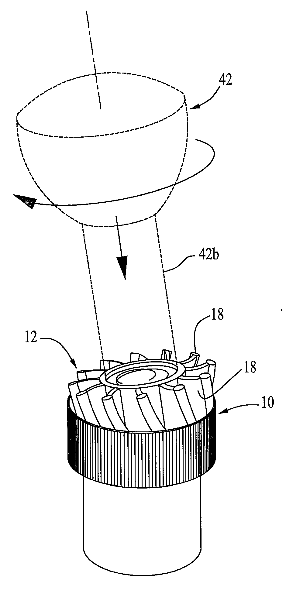
[0016]Referring now in detail to the drawings, the impeller installation tool 10 of the present invention is configured to facilitate the installation of an impeller 12 into the impeller cavity 14 of a water pump 16, all of which are illustrated in FIG. 1. The water pump 16 for which tool 10 is particularly designed is a raw water pump used in marine engines, although the tool could be used in other applications. The impeller 12 is a representative configuration of impellers employed in such applications and comprises a plurality of flexible blades 18, a hub 20 circumscribing a water pump shaft receiving channel 22 and defining a keying feature 24 adapted to mate with a corresponding keying feature 26 on the pump shaft 28. As illustrated in FIG. 1, the water pump shaft 28 is provided with a rectangular key 26 that is adapted to be received within a correspondingly configured key slot 24 in the impeller hub. It is to be understood that a wide variety of keying configurations, includi...


PUM

PropertyMeasurementUnit
angle of inclinationaaaaaaaaaa
radial thicknessaaaaaaaaaa
angleaaaaaaaaaa

Abstract

A tool for installing a flexible impeller on a drive shaft in the impeller cavity in a water pump including a gripping surface extending about an upper portion of the tool and an open ended channel extending axially through the tool for receiving and releasably retaining a flexible impeller therein in a compressed state. The channel has an upper portion circumscribed by an annular outwardly inclined impeller abutment surface and a lower constant radius portion circumscribed by a depending cylindrical wall. The inclined impeller abutment surface terminates in the constant radius portion.

Description

BACKGROUND OF THE INVENTION[0001]The present invention relates to a tool for installing flexible impellers in water pumps, particularly raw water pumps in marine applications. Typically, these impellers are installed by hand which requires pressing the impeller against the cam surface that is formed on an upper side of the impeller cavity wall in the water pump while concurrently rotating the impeller into alignment with the water pump drive shaft such that the key, serrations, flat surface(s) or other keying means on the impeller hub is aligned with the corresponding groove or other keying means on the water pump drive shaft. The impeller is then urged downwardly onto the shaft while being rotated with the shaft and against the stationary cam and cavity wall so as to uniformly deform and align the impeller blades within the impeller cavity. The impeller is then pressed to the bottom of the cavity for rotation therein with the impeller blades uniformly pressing against the impeller ...

Claims


Application Information

Patent Timeline
Patent Type & Authority Applications(United States)
IPC IPC(8): B25B27/02
CPCB25B27/00B25B27/02F04C5/00Y10T29/53909F04C2230/604Y10T29/53943Y10T29/49826F04C2230/60
Inventor PECHERZEWSKI, ANDRZEJ
Owner PECHERZEWSKI ANDRZEJ
Why Eureka
Try Eureka