Sagnac interferometer-type fiber-optic current sensor

Inactive Publication Date: 2011-06-16
KK TOSHIBA
View PDF14 Cites 24 Cited by
  • Summary
  • Abstract
  • Description
  • Claims
  • Application Information

AI Technical Summary

Problems solved by technology

Moreover, the change of the phase modulation efficiency by such phase modulators is also caused by the degradation of the phase modulator itself besides the temperature change.
In such conventional modulation method, even if the magnitude of the phase modulation actually applied to the light changes, the modulation system is not equipped with a feedback system at all by which the feedback operation is adjusted by detecting the change of the magnitude.
Furthermore, if a polarization extinction ratio in a propagation path of light, especially between a phase modulator and a quarter-wave plate changes, it causes a problem that the sensing output of the Sagnac interferometer-type fiber-optic current sensor changes, and the measurement accuracy is also reduced.
Therefore, it is difficult to keep the polarization extinction ratio stable between the phase modulator and the quarter-wave plate.
Thus, the deterioration of the polarization extinction ratio may take place in any portions of the polarizer, the phase modulator and the polarization maintaining fiber to optically connect the optical components, and results in change of the sensing output of the optical current sensor.
Therefore, the linearity of the input-and-output characteristic deteriorates, and the measurement accuracy also falls due to the change of the sensed output of the current sensor.
In this case, more than two phase modulators are required, and unless the phase modulation efficiency of two phase modulators is not the same, it is difficult to measure correctly the offset phase amount from the voltage applied to the phase modulator.
Therefore, the conventional method results in problems that the measurement accuracy falls, the cost is raised due to the use of two or more phase modulators, and the reliability of the sensor falls due to the increase in the number of parts used.

Method used


Image

  • Sagnac interferometer-type fiber-optic current sensor
  • Sagnac interferometer-type fiber-optic current sensor
  • Sagnac interferometer-type fiber-optic current sensor

Examples


first embodiment

1. First Embodiment

[0045]Next, the Sagnac interferometer-type fiber-optic current sensor according to the first embodiment of the present invention is explained below with reference to FIGS. 1 to 12. Hereinafter, the basic structure of the optical current sensor according to the first embodiment and fundamental operation shall be explained, and the Jones matrix shall be used to explain the behavior of the light.

[0046]First, the basic structure of the Sagnac interferometer-type fiber-optic current sensor according to the first embodiment is explained with reference to FIG. 1. FIG. 1 is a figure showing the basic structure of the Sagnac interferometer-type fiber-optic current sensor (Sagnac interferometer-type optical CT).

[0047]As shown in FIG. 1, the Sagnac interferometer-type fiber-optic current sensor includes a signal processing unit 100 which is composed of a light source driving circuit 101 described later, a light source 102, a fiber coupler 103, an optical filter 104, a phase ...

second embodiment

2. Second Embodiment

[0174]Next, the Sagnac interferometer-type fiber-optic current sensor according to the second embodiment is explained with reference to FIGS. 13 to 18. In the second embodiment, since the structures other than the phase modulator driving circuit 108 is the same as those of the first embodiment, the explanation is omitted and the same mark or symbol is denoted.

[0175]The feature of the second embodiment is to set P1ω to “0” at all times by controlling the phase modulation depth δ using the phase modulator driving circuit 108 as shown in FIG. 18.

[0176]Next, the control of the phase modulation depth δ to set P1ω to “0” by the phase modulator driving circuit 108 is explained hereinafter. In the explanation about the behavior of the light, the Jones matrix is used like the first embodiment.

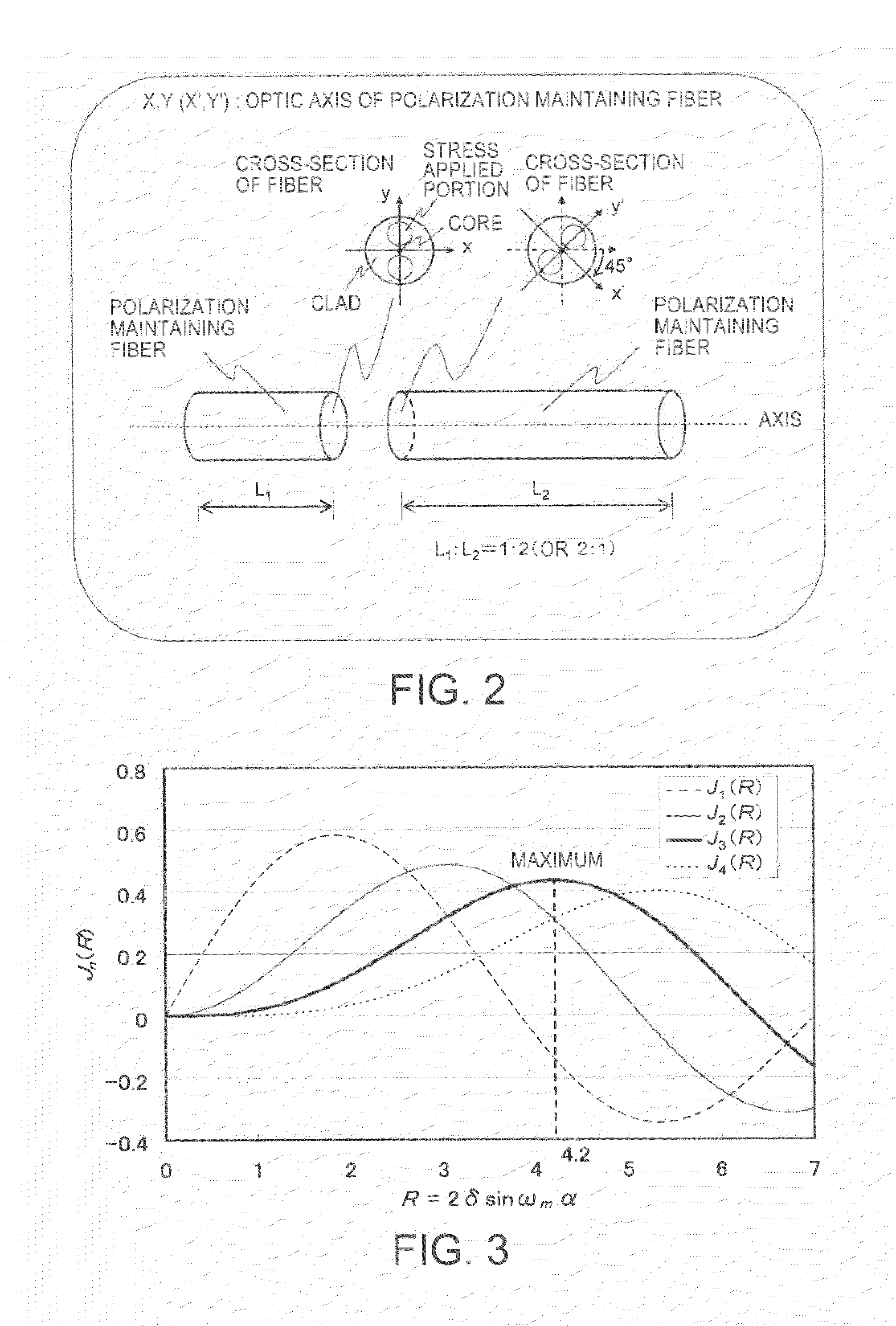
[0177]First, in the above equation 31 showing the first-order harmonics, it is necessary to set J1(R) to “0” in order to set P1ω to “0” regardless of the axial misalignment angle θc ...

third embodiment

3. Third Embodiment

[0216]Next, the structure of the Sagnac interferometer-type fiber-optic current sensor according to the third embodiment is explained below. In the third embodiment, since the components other than the phase modulator driving circuit 108 is the same as those of the first embodiment, the explanation about the components shall be omitted and the same marks or symbols is denoted.

[0217]The feature of the third embodiment is that R=2δ sin ωmα is set to be larger than 0 and smaller than 7 in the phase modulator driving circuit 108 so that P1ω does not become “0” except R=2δ sin ωmα≈3.83 as explained later.

[0218]Next, the control of the phase modulator by the phase modulator driving circuit 108 according to the third embodiment is explained below including the prior problems.

[0219]In the second embodiment, the phase modulator driving circuit 108 controls the phase modulator so as to be P1ω=0. However, when the current I to be measured is “0”, that is, when θf=0, P1ω beco...


PUM


Abstract

In one embodiment, a Sagnac interferometer-type fiber-optic sensor includes a synchronous detection circuit to carry out synchronous detection of detected light signal with a phase modulation angular frequency of a phase modulator. A signal processing circuit calculates and outputs the magnitude of current to be measured using the signal detected in the synchronous detection circuit. A phase modulator driving circuit controls the driving of the phase modulator. The phase modulator driving circuit controls a phase modulation depth of the phase modulator so that the amplitude of the second-order harmonics and the fourth-order harmonics obtained by carrying out the synchronous detection of the detected light signal with the phase modulation angular frequency becomes the same.

Description

CROSS-REFERENCE TO RELATED APPLICATION[0001]This application is based upon and claims the benefit of priority from prior Japanese Patent Application No. 2009-281021, filed Dec. 10, 2009, the entire contents of which are incorporated herein by reference.FIELD[0002]The present invention relates to a Sagnac interferometer-type fiber-optic current sensor using optical phase modulation.BACKGROUND[0003]Various types of Sagnac interferometer-type fiber-optic current sensors using optical phase modulation are proposed. For example, “All-fiber Sagnac current sensor” shown in FIG. 19 (refer to literature 1), the “Reciprocal reflection interferometer for a fiber-optic Faraday current sensor” shown in FIG. 20 (refer to literature 2), “Production method for a sensor head for optical current sensor” shown in FIG. 21 (refer to National Publication of translated version No. 2005-517961) and “Fiber optic current sensor” shown in FIG. 22 (refer to National Publication of translated version No. 2002-5...

Claims


Application Information

Patent Timeline
IPC IPC(8): G01B9/02
CPCG01R19/0092G01R15/246G01D5/35322
Inventor SASAKI, KINICHITAKAHASHI, MASAOHIRATA, YUKIHISA
Owner KK TOSHIBA
Why Eureka
Try Eureka