
Sheet feeding device and image forming apparatus

Inactive Publication Date: 2011-06-16
CANON KK
View PDF5 Cites 13 Cited by
  • Summary
  • Abstract
  • Description
  • Claims
  • Application Information

AI Technical Summary

Benefits of technology

[0010]The present invention is to provide a sheet feeding device that can prevent breakage, deformation, and the like during transport without an increase in cost, which is otherwise caused by a dedicated packaging material or a fixing member and without requiring a labor of a user.
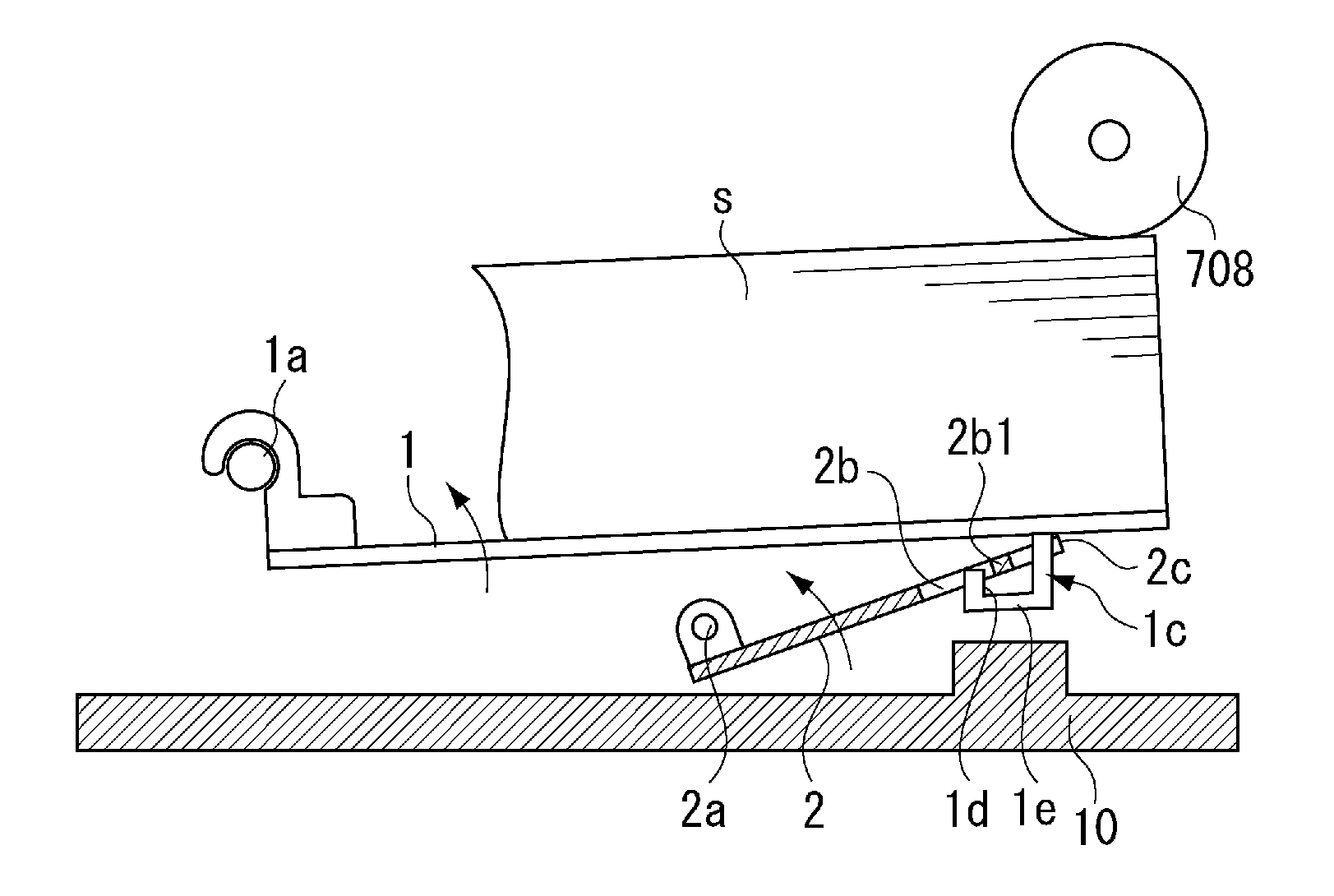
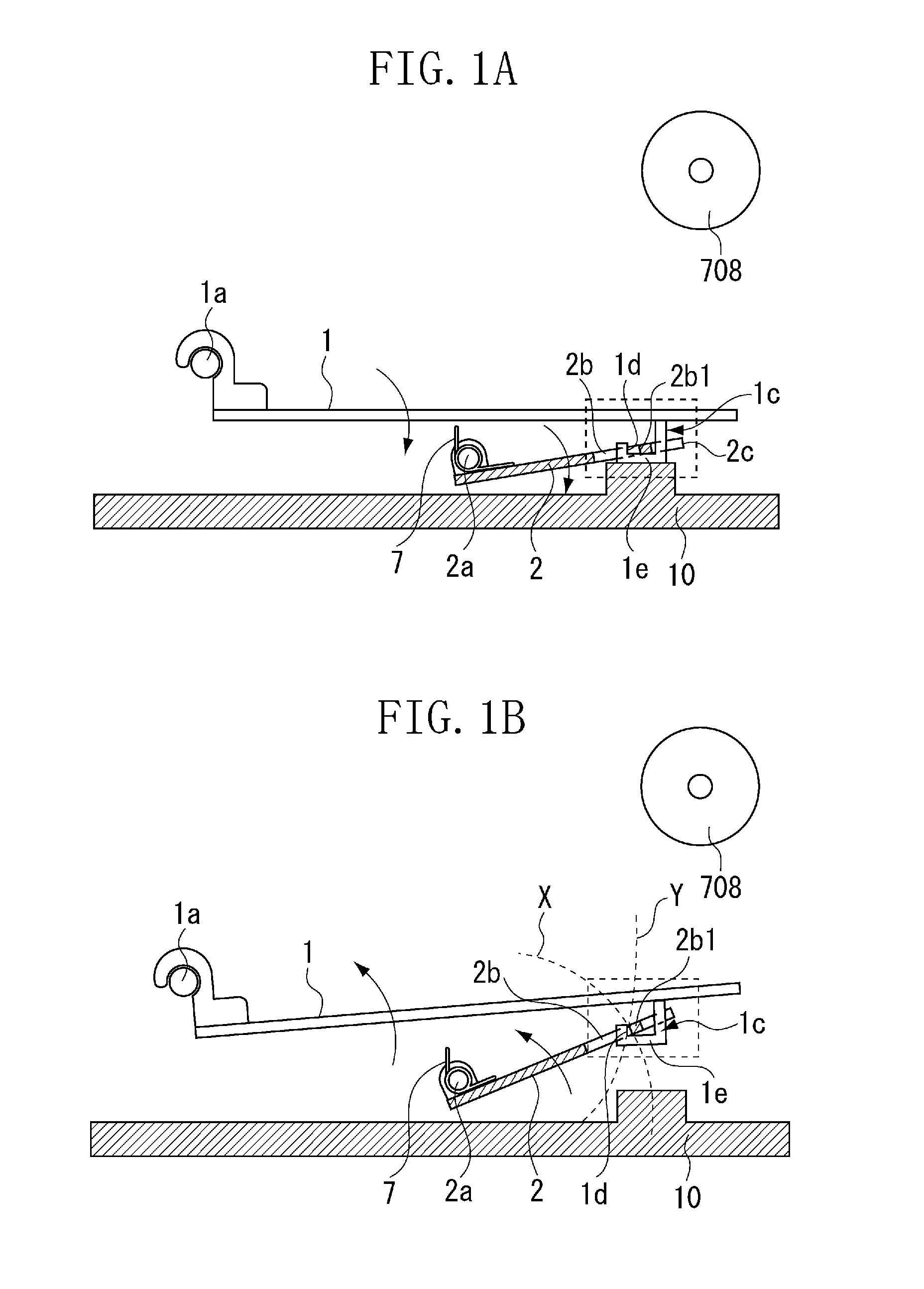
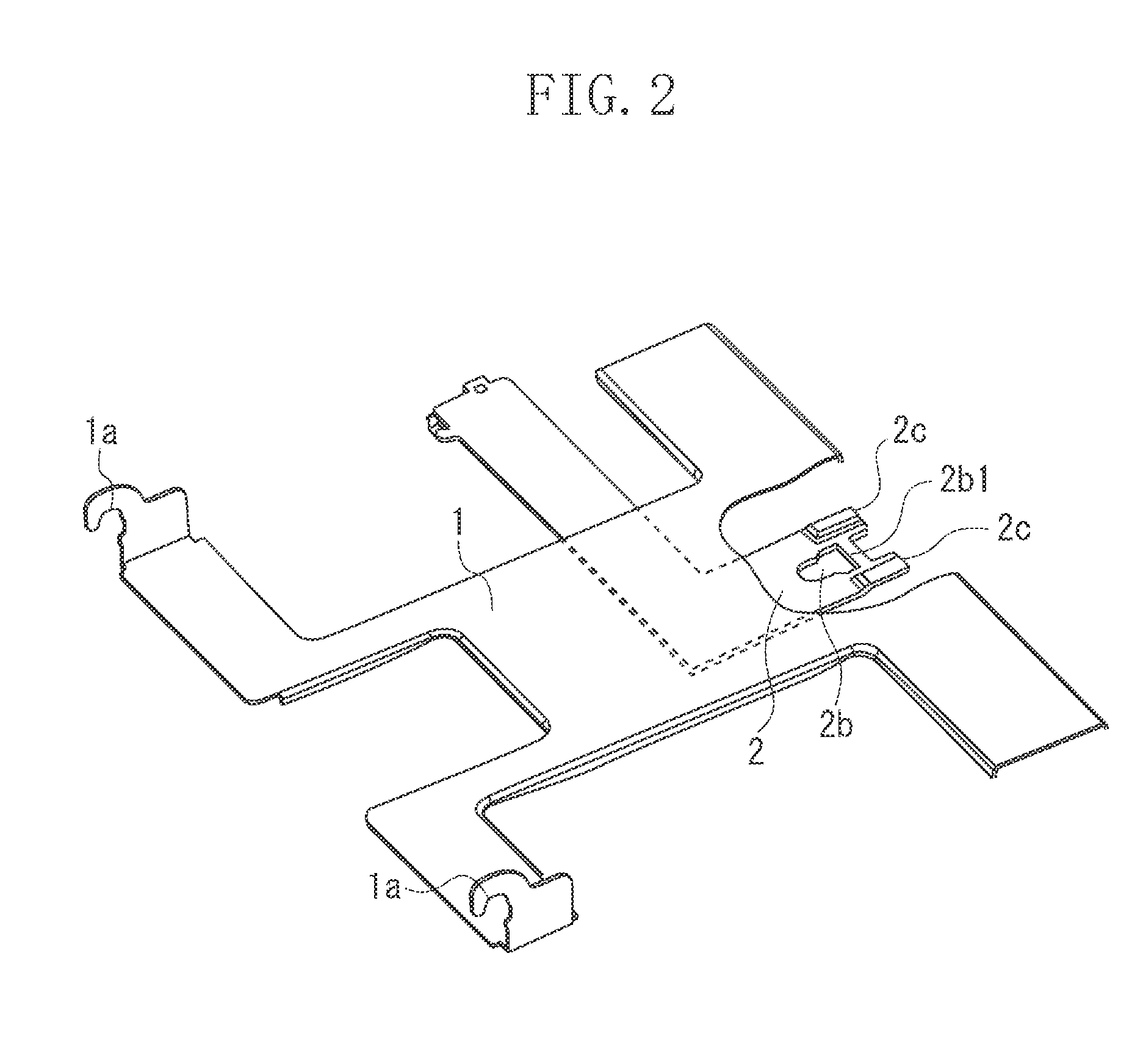
[0011]According to an aspect of the present invention, there is provided a sheet feeding device that feeds sheets by a sheet feeding unit from a sheet feeding cassette storing the sheets, including a cassette case, a lifting plate that is rotatably supported in the cassette case, on which the sheets are placed, and a pressing member that is rotatably supported below the lifting plate and presses the sheet to the sheet feeding unit by lifting up the lifting plate, wherein positions of rotation centers of the lifting plate and the pressing member are varied from each other in such a manner that a rotation track of an engaging member provided on the lifting plate and a rotation track of an engaged member provided on the pressing member engaged with the engaging member, intersect with each other, so that the engaged member restricts the engaging member at the intersection position of the rotation tracks to restrict rotation of the lifting plate when the lifting plate moves upward ahead of a lifting operation of the pressing member.

Problems solved by technology

Since the lifting plate is not fixed though it is attached to the cassette case, the lifting plate is caused to tumble due to vibration during transport such as shipping from a factory to break other parts of the sheet feeding cassette or is deformed in some cases.
However, the packaging material or the fixing member is used only for the transport if the lifting plate is fixed using the fixing member such as the packaging material or the dedicated fixing member.
In short, the packaging material or the fixing member entails an increase in cost.
Further, if the lifting plate is fixed using the rear end restricting member for sheet position restriction, an extra labor of the user is required to move the rear end restricting member after unpacking the apparatus.
Also, an elevation mechanism for lifting up the lifting plate may be broken when the image forming apparatus is actuated without moving the rear end restricting member.

Method used


Image

  • Sheet feeding device and image forming apparatus
  • Sheet feeding device and image forming apparatus
  • Sheet feeding device and image forming apparatus

Examples


Embodiment Construction

[0022]Various exemplary embodiments, features, and aspects of the invention will be described in detail below with reference to the drawings.

[0023]Hereinafter, a first exemplary embodiment of a sheet feeding device and an image forming apparatus according to the present invention will be described with reference to FIGS. 1A to 7. Dimensions, materials, and relative positions of component parts described in the first exemplary embodiment do not limit the scope of the present invention unless described particularly specifically.

[0024]Hereinafter, an entire configuration of the image forming apparatus provided with the sheet feeding device to which the present invention is adapted will briefly be described. FIG. 7 is a sectional view illustrating an entire configuration of a color laser printer (hereinafter referred to as printer) 100 which is one aspect of the image forming apparatus.

[0025]The printer 100 illustrated in FIG. 7 is provided with an image forming unit including four proc...


PUM


Abstract

A sheet feeding device that feeds sheets by a sheet feeding unit from a sheet feeding cassette storing the sheets, in which positions of rotation centers of a lifting plate and a lifting plate pressing member are varied from each other in such a manner that a rotation track of an edge of an opening of the lifting plate pressing member and a rotation track of a vertical surface of an engaging member provided on the lifting plate intersect with each other, so that the edge is engaged with the vertical surface at the intersection position of the rotation tracks to restrict rotation of the lifting plate when the lifting plate moves upward before a lifting operation of the lifting plate pressing member.

Description

BACKGROUND OF THE INVENTION[0001]1. Field of the Invention[0002]The present invention relates to a sheet feeding device mounted on an image forming apparatus such as a laser beam printer and a copying machine.[0003]2. Description of the Related Art[0004]An image forming apparatus is provided with a sheet feeding device for storing and feeding sheets. The sheet feeding device includes a sheet feeding cassette serving as a sheet storing device, a sheet feeding roller for feeding the sheets stored in the sheet feeding cassette, and a separation unit for separating the sheets to be fed by the sheet feeding roller one by one. An image is formed on the sheet fed by the sheet feeding device in an image forming unit provided in the image forming apparatus. The sheet feeding cassette includes a lifting plate that is attached rotatably to a cassette case, and the lifting plate is lifted up by a pressing member, so that the sheets supported by the lifting plate are pressed against the sheet fe...

Claims


Application Information

Patent Timeline
IPC IPC(8): B65H1/14
CPCB65H1/14B65H2801/06B65H2405/1117
Inventor NISHITANI, SHUJIUEDA, SHINICHI
Owner CANON KK
Learn More