Latitudinal iso-line scribe, stitching, and simplified laser and scanner controls

Inactive Publication Date: 2011-06-16
FORTIX
View PDF17 Cites 3 Cited by
  • Summary
  • Abstract
  • Description
  • Claims
  • Application Information

AI Technical Summary

Benefits of technology

[0008]Systems and methods for improved stitching while laser scribing are provided. Many embodiments may provide for improved control, as well as the ability to scribe in multiple directions and / or patterns without rotating the workpiece. Systems and methods in accordance with many embodiments provide for general purpose, high-throughput, direct patterning laser scribing on large film-deposited substrates. These systems and methods may be particularly effective in scribing single junction solar cells and thin-film multi junction solar cells.
[0010]In many embodiments, a method for improved stitching while scribing a workpiece is provided. The method comprises generating a first scribe on the workpiece; generating a second scribe on the workpiece; and controlling at least one of a velocity of at least one scanner used to direct at least one laser beam to form the first and second scribes, a switching of at least one laser used to form the first and second scribes, and patterning of the scribe segments such that the first scribe at least partially overlaps with the second scribe on the workpiece. Alternatively a third scribe segment can be used in the stitching process; the process involves selecting a stitch point of the first and second scribe segments to substantially correspond to a position of a third scribe segment, such that the third scribe segment will function to connect the first and second scribe segments upon an offset of the first and second scribe segments on the workpiece.

Problems solved by technology

Further, under this fixed laser beam approach, the beam path from the scribing laser to the workpiece can be long.
This long fixed beam path between the laser and the workpiece raises beam convergence and stability issues.
In order to accommodate the workpieces, which in one example can be as large as one square meter, this stage also has to be large, making it difficult to ship from the manufacturer site to the user site.
Furthermore, when using two or more lasers to scribe a pattern, complications arise.

Method used


Image

  • Latitudinal iso-line scribe, stitching, and simplified laser and scanner controls
  • Latitudinal iso-line scribe, stitching, and simplified laser and scanner controls
  • Latitudinal iso-line scribe, stitching, and simplified laser and scanner controls

Examples


Embodiment Construction

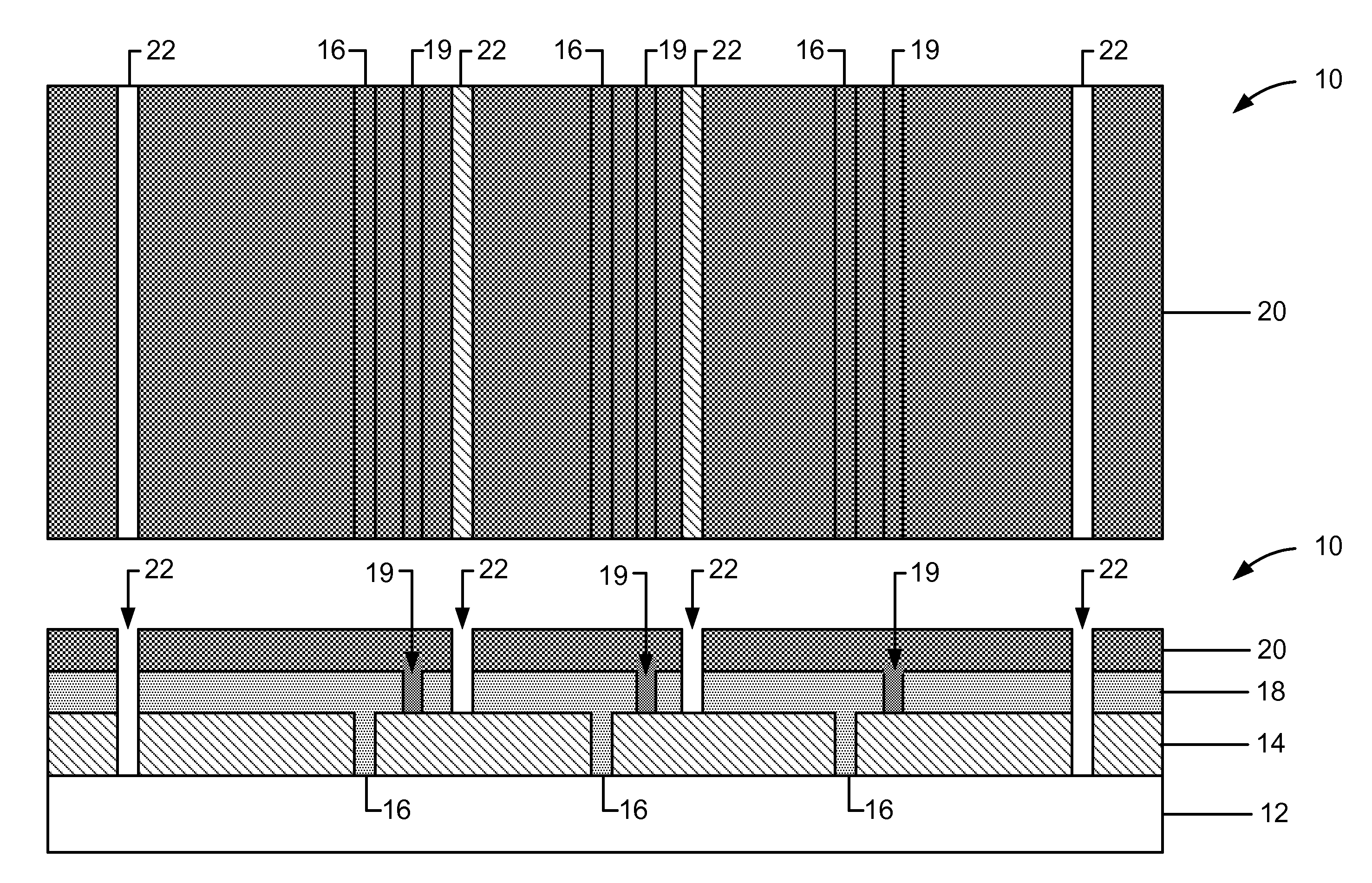
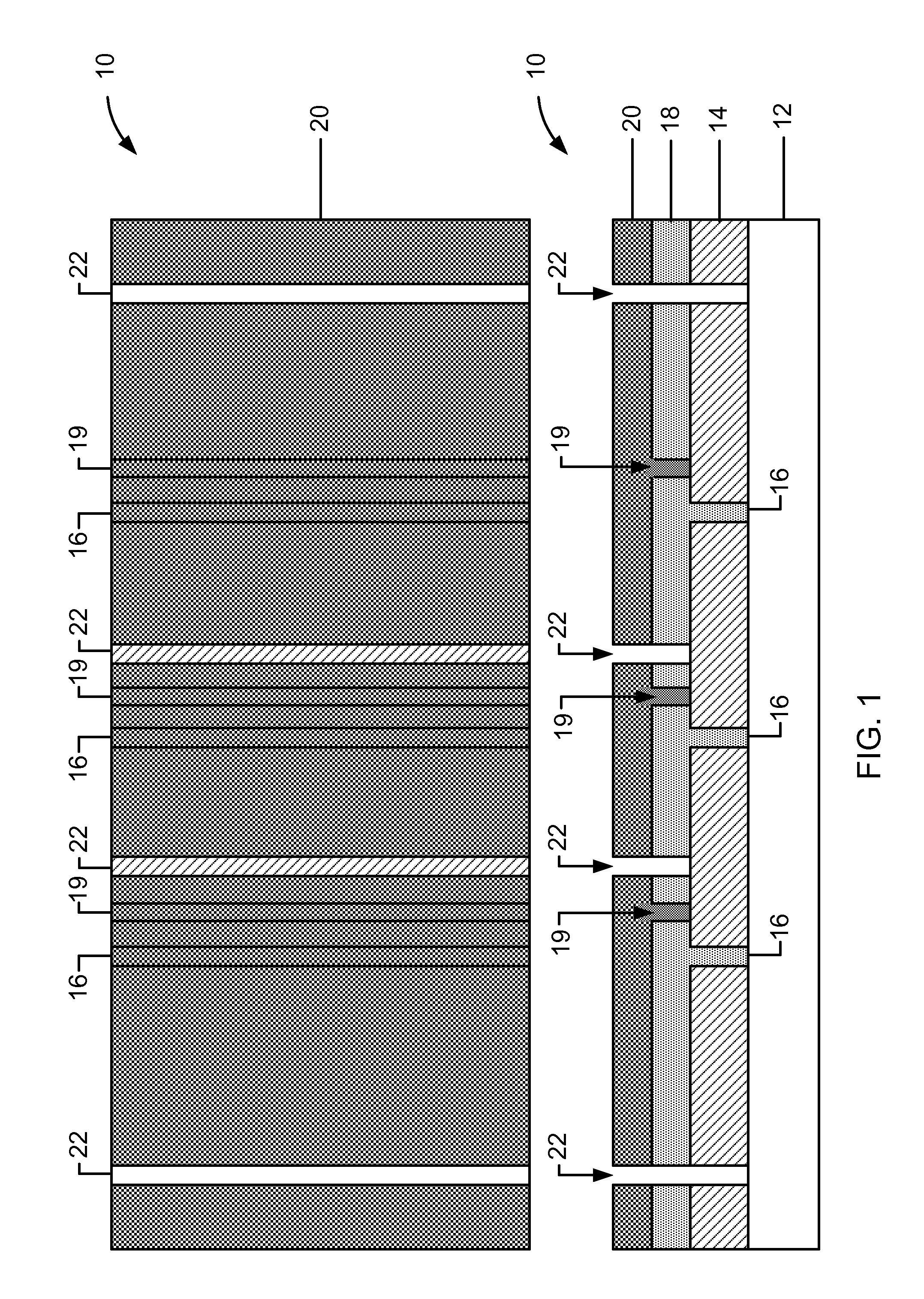
[0029]Systems and methods in accordance with many embodiments of the present disclosure can overcome one or more of the aforementioned and other deficiencies in existing scribing approaches. Many embodiments can provide for improved control as well as the ability to scribe in multiple directions and / or patterns without rotating a substrate. Systems and methods in accordance with many embodiments provide for general purpose, high-throughput, direct patterning laser scribing on large film-deposited substrates. Such systems and methods allow for bi-directional scribing, patterned scribing, arbitrary pattern scribing, and / or adjustable pitch scribing, without having to rotate a workpiece.

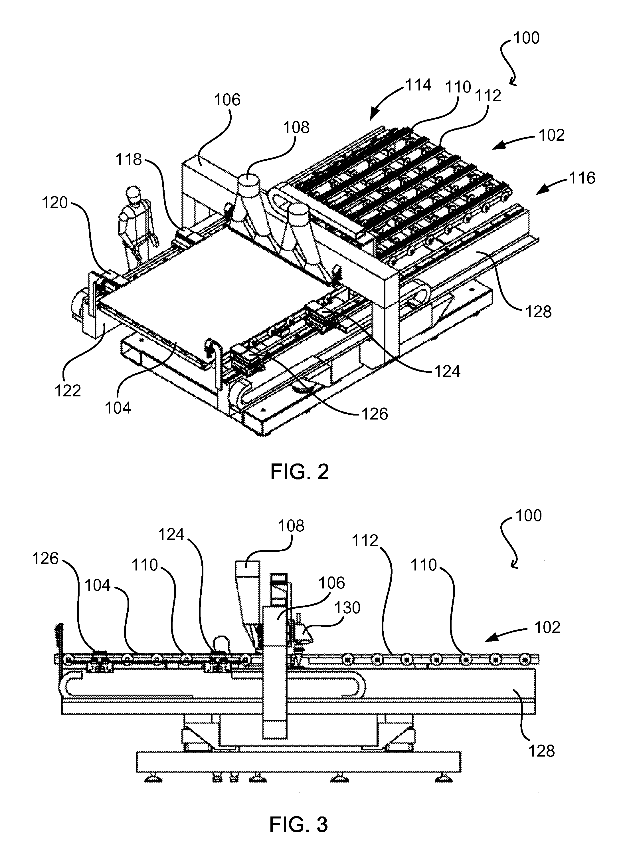
[0030]Systems and methods in accordance with many embodiments provide for laser scribing using simple longitudinal glass movement and multiple laser scanners to scribe workpieces, for example, film-deposited substrates used in some solar cell devices. The workpiece can be moved during scribing, and lase...


PUM

PropertyMeasurementUnit
Thicknessaaaaaaaaaa
Poweraaaaaaaaaa
Dimensionaaaaaaaaaa

Abstract

The stitch points of segments formed into a workpiece by laser scribing can be improved by controlling aspects such as the velocity of the scanner and the switching points of the laser, such as to allow for lead-in, lead-out, and overlap periods. The locations of the stitch points also can be selected to coincide with existing lines such that the existing lines will function to connect the segments in the event of an offset.

Description

CROSS-REFERENCES TO RELATED APPLICATIONS[0001]This application claims the benefit of U.S. Prov. Patent Application No. 61 / 231,971 filed Aug. 6, 2009, and titled “LATITUDINAL ISO-LINE SCRIBE, STITCHING, AND SIMPLIFIED LASER AND SCANNER CONTROLS” and incorporated herein by reference for all purposes.BACKGROUND OF THE INVENTION[0002]Many embodiments described herein relate generally to the scribing of materials, as well as systems and methods for scribing materials. These systems and methods can be particularly effective in scribing single junction solar cells and thin-film multi junction solar cells.[0003]Current methods for forming thin-film solar cells involve depositing or otherwise forming a plurality of layers on a substrate, for example, a glass, metal or polymer substrate suitable to form one or more p-n junctions. An example of a solar cell has an oxide layer (e.g., a transparent conductive oxide (TCO)) deposited on a substrate, followed by an amorphous-silicon layer and a met...

Claims


Application Information

Patent Timeline
IPC IPC(8): B23K26/00
CPCB23K26/041B23K26/0807B23K26/367H01L31/046H01L31/0392Y02E10/50H01L31/022425B23K26/042B23K26/082B23K26/364H01L31/03921H01L31/0463
Inventor FAN, JIAFAMANENS, ANTOINE P.
Owner FORTIX
Why Eureka
Try Eureka