Photovoltaic system

a photovoltaic system and photovoltaic technology, applied in the direction of thermal-pv hybrid energy generation, lighting and heating apparatus, heating types, etc., can solve the problem of overall system efficiency suffers

Inactive Publication Date: 2011-06-16
GIRITSCH JOHANN +3
View PDF5 Cites 9 Cited by
  • Summary
  • Abstract
  • Description
  • Claims
  • Application Information

AI Technical Summary

Benefits of technology

[0006]The basic concept of the present invention lies in dissipating the process heat generated during operation of the photovoltaic elements and utilizing the energy thereof. On the one hand, this has the effect that the efficiency of electricity generation by the photovoltaic elements is improved, as the switching off of the inverters as a result of exceeding the maximum operating temperature can substantially be avoided. Furthermore, this extracted process heat is fed to a heat storage unit which then in turn feeds the stored heat to different consumption circuits as required.
[0008]According to an advantageous embodiment, it is possible to arrange an insulating layer below the cooling unit in order to increase the efficiency.
[0010]To control the temperature relationships in the first carrier medium circuit, it is particularly advantageous to use a first circulating pump which is preferably fed and switched by a thermostat which is provided within the first carrier medium circuit and on the heat storage unit. The power of the circulating pump can be variably adjusted in an advantageous manner.

Problems solved by technology

The efficiency of the overall system suffers from this.

Method used


Image

  • Photovoltaic system
  • Photovoltaic system
  • Photovoltaic system

Examples


Embodiment Construction

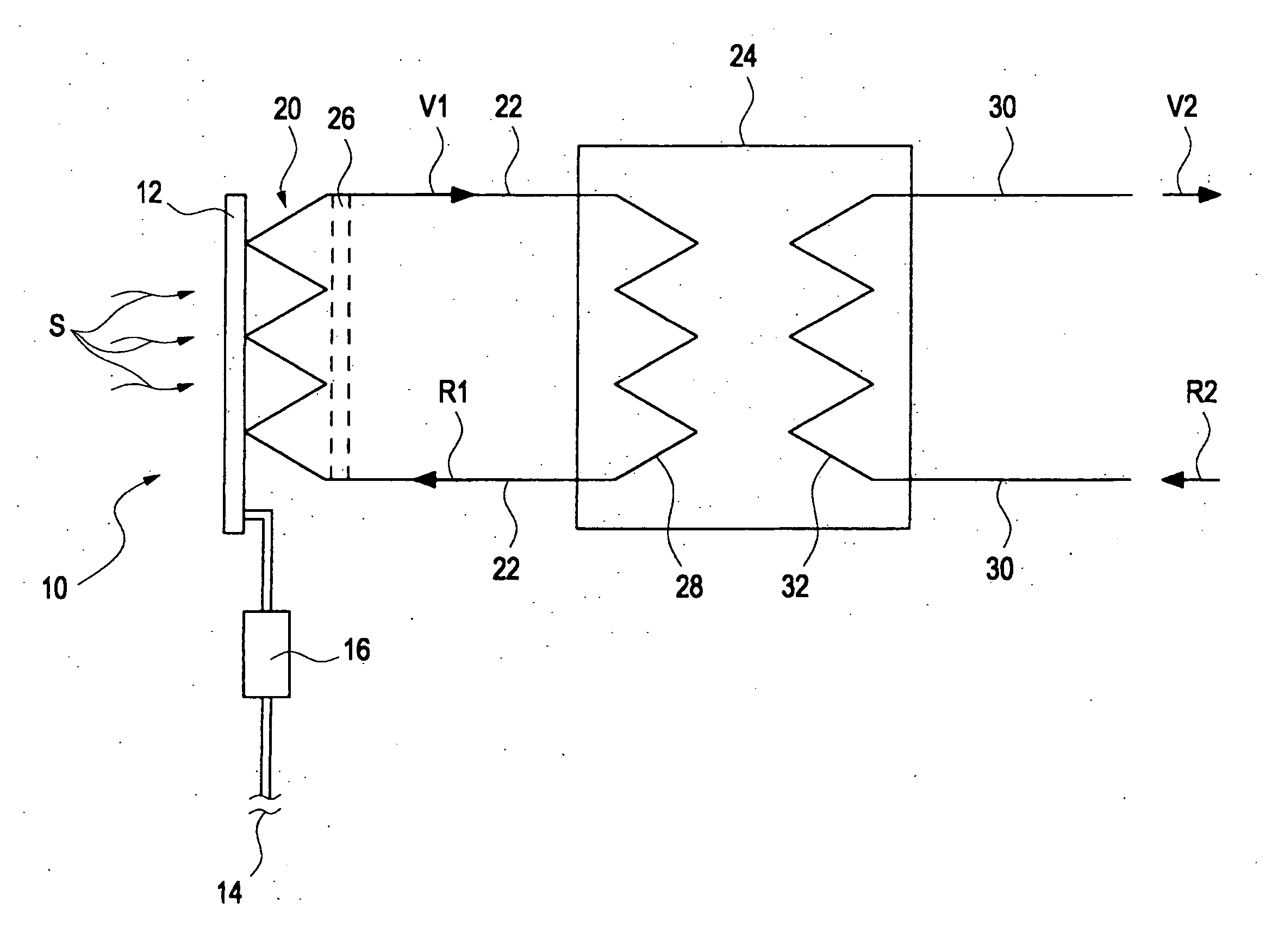
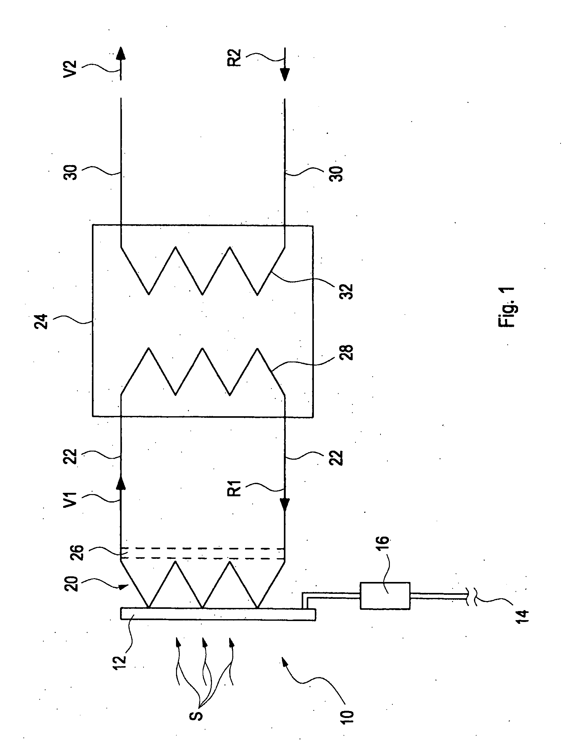
[0020]A photovoltaic system 10 having a photovoltaic element 12 shown by way of example which is subjected to solar irradiation S from above is depicted highly schematically in FIG. 1. The photovoltaic element 12 is wired to an inverter 16 which feeds the electrical energy generated by the photovoltaic element 12 into a power supply network which is shown symbolically in FIG. 1.

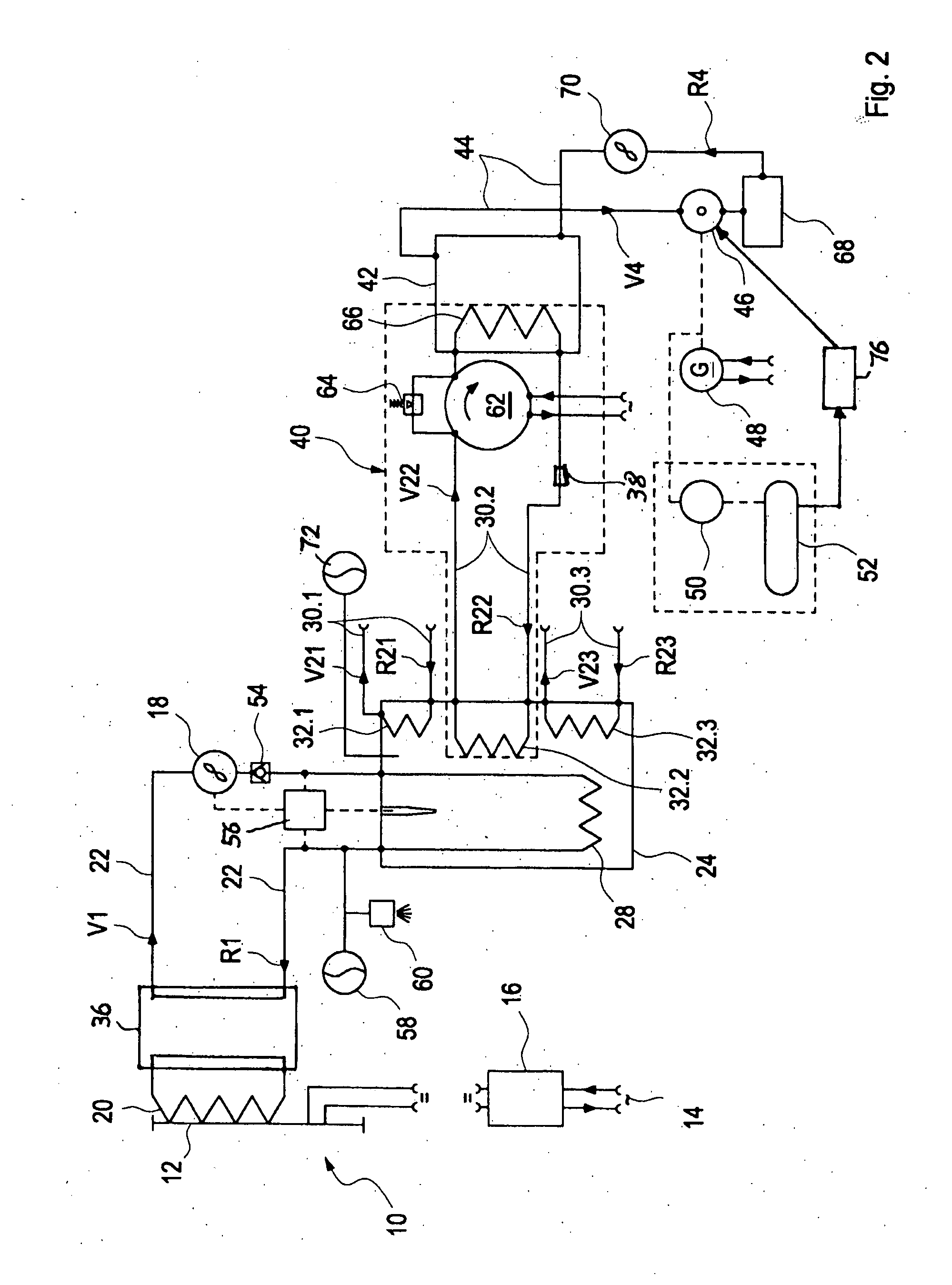
[0021]A cooling unit 20, which communicates with the first heat pump 36 via a heat pump circuit 34, is arranged on the underside of the photovoltaic element 12. Furthermore, the first heat pump 36, which is shown highly schematically in FIG. 1, is incorporated into a first carrier medium circuit 22 having a feed V1 and a return R1, the first carrier medium circuit 22 being routed partially within a heat storage unit 24 which is filled with a heat storage medium. The first heat pump 36 is used to achieve a temperature of approx. 60° to 70° C. (Celsius) in the heat storage unit 24.

[0022]The first carrier medium...


PUM


Abstract

A photovoltaic system includes planar photovoltaic elements that generates electricity from solar irradiation and feed it into a power grid and / or a battery unit. A cooling coil that communicates with a first heat pump via a heat pump circuit is arranged under each photovoltaic element and feeds heat generated during operation of the photovoltaic element to the first heat pump, which communicates with a first carrier medium circuit containing a first carrier medium. A heat accumulator unit containing a heat accumulating medium is arranged in the first carrier medium circuit, the thermal energy of the first carrier medium being transferred to the heat accumulating medium within the heat accumulator unit. In addition, at least one other heat consumption circuit containing a second carrier medium communicates with the heat accumulator unit, and the thermal energy of the heat accumulating medium is transferred to the second carrier medium as needed.

Description

CROSS-REFERENCE TO RELATED PATENT APPLICATIONS[0001]This application is a U.S. National Phase Application under 35 U.S.C. §371 of International Patent Application No. PCT / DE2009 / 000923, filed Jul. 1, 2009, and claims the benefit of German Patent Application No. 202008008747.3, filed Jul. 2, 2008, all of which are incorporated by reference herein. The International Application was published in German on Jan. 7, 2010 as International Publication No. WO 2010 / 000240 under PCT Article 21(2).FIELD OF THE INVENTION[0002]The present invention relates to a photovoltaic system having planar photovoltaic elements, which when subjected to solar irradiation from above generate electrical energy which is fed into a power supply network and / or is supplied to an electricity storage unit.BACKGROUND OF THE INVENTION[0003]The use of photovoltaic systems for converting the sun's energy into electrical energy is well known. The planar photovoltaic elements of such photovoltaic systems are mounted for ex...

Claims


Application Information

Patent Timeline
Patent Type & Authority Applications(United States)
IPC IPC(8): H01L31/058F24D18/00
CPCF03G6/001F24D11/0221F24D2200/14F24H2240/00F24J2/04F24J2/42H02S40/44Y02B10/70Y02B30/126Y02E10/46Y02E10/60H02S40/32Y02B10/20F24D2200/02F24S10/00F24S90/00Y02E10/50F24D18/00F24D2103/17F24D2103/13F24D2101/10F24D2101/40
Inventor GIRITSCH, JOHANN
Owner GIRITSCH JOHANN
Why Eureka
Try Eureka