Three part laminated construction

a technology of laminated construction and three parts, which is applied in the direction of transportation and packaging, synthetic resin layered products, chemistry apparatus and processes, etc., can solve the problems of difficult to easily change the shape of the device, difficult to easily change the size of conventional oil draining devices, and difficult to purchase smaller and larger devices

Inactive Publication Date: 2011-06-09
LOHMEIER KEVIN F
View PDF15 Cites 5 Cited by
  • Summary
  • Abstract
  • Description
  • Claims
  • Application Information

AI Technical Summary

Benefits of technology

[0028]Another objective of the invention is to provide a surface construction for protecting rescue personnel from the dangers of injury and damage to equipment from jagged edges such as formed by the cutting off of parts of vehicles and equipment to extricate persons from the vehicle or other dangerous situations.
[0029]Another objec...

Problems solved by technology

Significant problems can result from such devices being fixed in configuration.
It is not possible to easily change the shape of the device to provide a custom way to drain oil or direct the flow of fluid to accommodate custom needs such as dictated by unusual engine configurations and drain port locations.
It is also not possible to easily change the sizes of conventional oil draining devices, other than perhaps cutting off the length of a rubber tube.
Consequently, smaller and larger size devices must often be purchased to accommodate special size limitations of particular needs.
Another disadvantage of conventional oil draining devices is that they often do not provide large surface flow area which would be convenient to collect and channel large volumes of fluid.
Another problem with conventional oil draining devices is that they are typically bulky, and cannot be conveniently stored in a compact form or limited space location.
Thus, while conventional oil draining devices may be suitable for the particular purpose to which they are intended to address, they are not easily adaptable for unusual circumstances, and their use can present difficulties in certain instances.
As one example, use of conventional oil draining devices can be a continuing problem in draining oil from certain aircraft engines where the oil filter is located in a difficult to reach place, and draining the...

Method used


Image

  • Three part laminated construction
  • Three part laminated construction
  • Three part laminated construction

Examples


Embodiment Construction

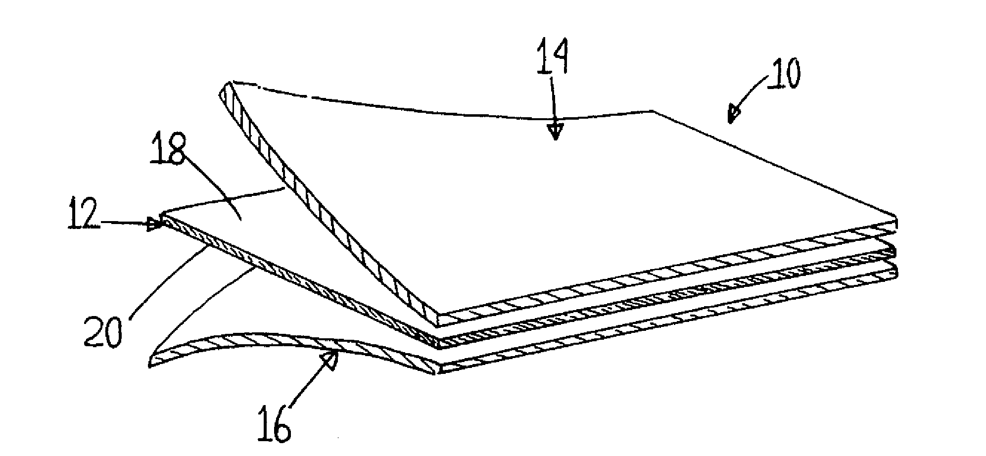
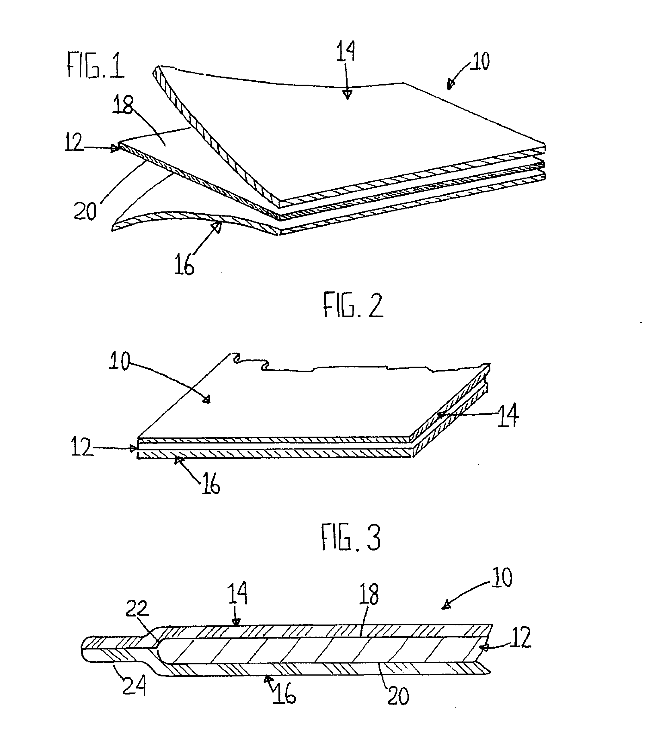
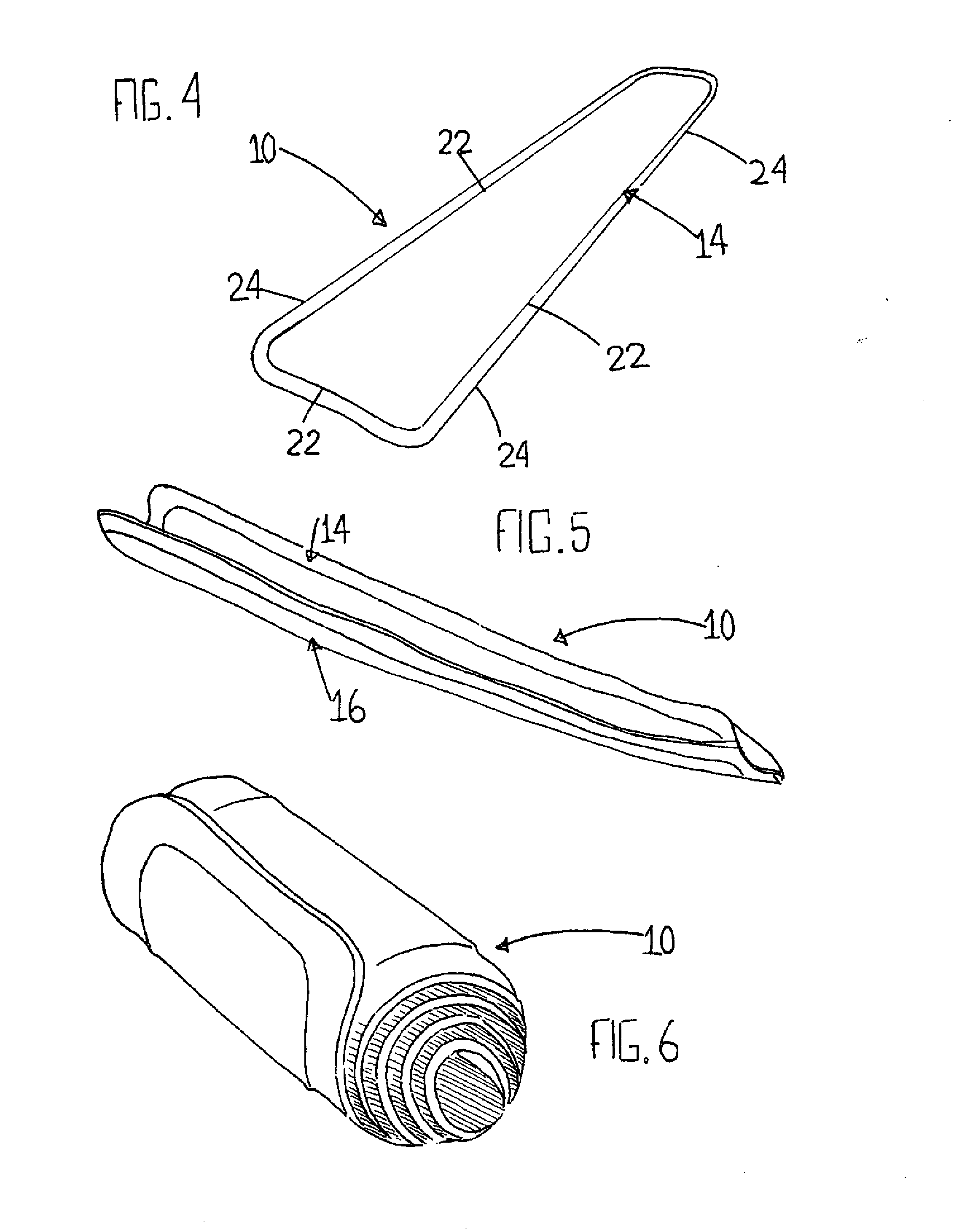
[0055]Turning now descriptively to the drawings, in which similar reference characters denote similar elements throughout the several views, there is shown a three-part laminated pliable hand-moldable surface construction 10 (see FIG. 4 for an overall perspective) which comprises three main layers. The center layer of the surface construction 10 is a pliable hand-moldable sheet of lead designated as item 12 (see FIGS. 1-3), both sides of which are covered with an appropriate pliable material layer 14, 16 such as thin rubber. This configuration establishes a three part laminated hand-moldable and pliable surface construction 10 which can be manually shaped to a desired configuration, optionally cut to a desired size, and is adaptable for many purposes, including but not limited to channeling the flow of liquid from one location to another, and fanning a protective cover over exposed jagged edges.

[0056]More particularly, the middle layer of the surface construction 10 is a sheet of le...


PUM

PropertyMeasurementUnit
Flow rateaaaaaaaaaa
Lengthaaaaaaaaaa
Electrical resistanceaaaaaaaaaa

Abstract

A three-part laminated surface construction can be shaped and molded by hand and will retain that shape until the particular need is met, such as controlling the flow of liquids and resins, or establishing a protective cover. The surface construction includes a center layer of pliable hand-moldable sheet with pliable sheet outer layers secured over the hand-moldable sheet. The perimeter of the pliable outer layers are secured together. The pliable hand-moldable sheet can be provided with diagonal slots to form quadrants for folding around and protection from sharp objects. In one form cloth inserted rubber material is used for the outer layers. In one form, a strap with loop and hook fastener is provided to aid in securing the protective cover in place.

Description

Cross-References to Related Applications[0001]This application claims priority as a continuation-in-part to U.S. Non-Provisional patent application Ser. No. 11 / 407,872, filed Apr. 20, 2006, U.S. Pat. No. 7,851,038, entitled “Three-Part Laminated Pliable Moldable Surface Construction” and to U.S. Provisional Patent Application Ser. No. 60 / 673,008, filed Apr. 20, 2005, U.S. Provisional Patent Application Ser. No. 60 / 692,523, filed Jun. 21, 2005, and U.S. Provisional Patent Application Ser. No. 60 / 722,614, filed Sep. 30, 2005, the specifications and drawings of which are incorporated herein by reference as if fully set forth.BACKGROUND OF THE INVENTION[0002]The present invention relates generally to a pliable hand-moldable surface construction.[0003]More specifically, the invention relates to a three-part laminated pliable hand-moldable surface construction which, while suitable for other uses, is particularly useful for channeling the flow of liquids and resins such as for draining en...

Claims


Application Information

Patent Timeline
IPC IPC(8): B32B3/10B32B15/00B32B15/06
CPCY10T428/24331B32B15/08B60R13/043B32B25/18Y10T428/1359Y10T428/1386Y10T428/31699Y10T428/31696Y10T428/31678
Inventor LOHMEIER, KEVIN F.
Owner LOHMEIER KEVIN F
Why Eureka
Try Eureka