
Virtual machine migration managing method, computer using the method, virtualizer using the method and computer system using the method

a virtual machine and managing method technology, applied in computing, instruments, electric digital data processing, etc., can solve problems such as the failure of the function of access control for an external device as an access target of the virtual machine, the inability to request the virtualizer, and the suspension of migration processing

Active Publication Date: 2011-06-02
HITACHI LTD
View PDF3 Cites 48 Cited by
  • Summary
  • Abstract
  • Description
  • Claims
  • Application Information

AI Technical Summary

Benefits of technology

[0011]According to the prior art, in an operation to move a virtual machine executing a job from a first physical machine to a second physical machine, the managing server executes a migration procedure while communicating with the physical machine as a migration source and the physical machine as a migration destination. The virtualizer on each of the physical machines processes a request from the managing server to appropriately transfer the setting of access control between the physical machines. It is hence possible to migrate the virtual machine to the second physical machine as the migration destination without deteriorating security.
[0017]It is therefore an object of the present invention to provide a computer system capable of moving a virtual machine from a first physical machine to a second physical machine independently of the managing server.

Problems solved by technology

However, if the managing server fails or if the communication between the managing server and the virtualizers is disconnected before the virtual machine is completely migrated, the request cannot be issued to the virtualizer and the migration processing is suspended.
Due to suspension of the migration processing, the function of access control for an external device as an access target of the virtual machine fails in some cases.
Therefore, it is likely that the contents of the storage volume are destroyed.
However, if the managing server is not restored or if the communication from the managing server to the physical machine of the migration source or destination is not restored, the recovery processing cannot be executed.
If the system waits for completion of the recovery job or if the virtual machine definition is once erased and is then created again for the recovery, the downtime due to the migration suspension is disadvantageously elongated.

Method used


Image

  • Virtual machine migration managing method, computer using the method, virtualizer using the method and computer system using the method
  • Virtual machine migration managing method, computer using the method, virtualizer using the method and computer system using the method
  • Virtual machine migration managing method, computer using the method, virtualizer using the method and computer system using the method

Examples


embodiment 1

[0039]Description will now be given of a first embodiment according to the present invention. In conjunction with the first embodiment associated with a system including virtualizers, description will be given of a configuration of a device for and a method of migrating a Virtual Machine (VM) through communication between virtualizers.

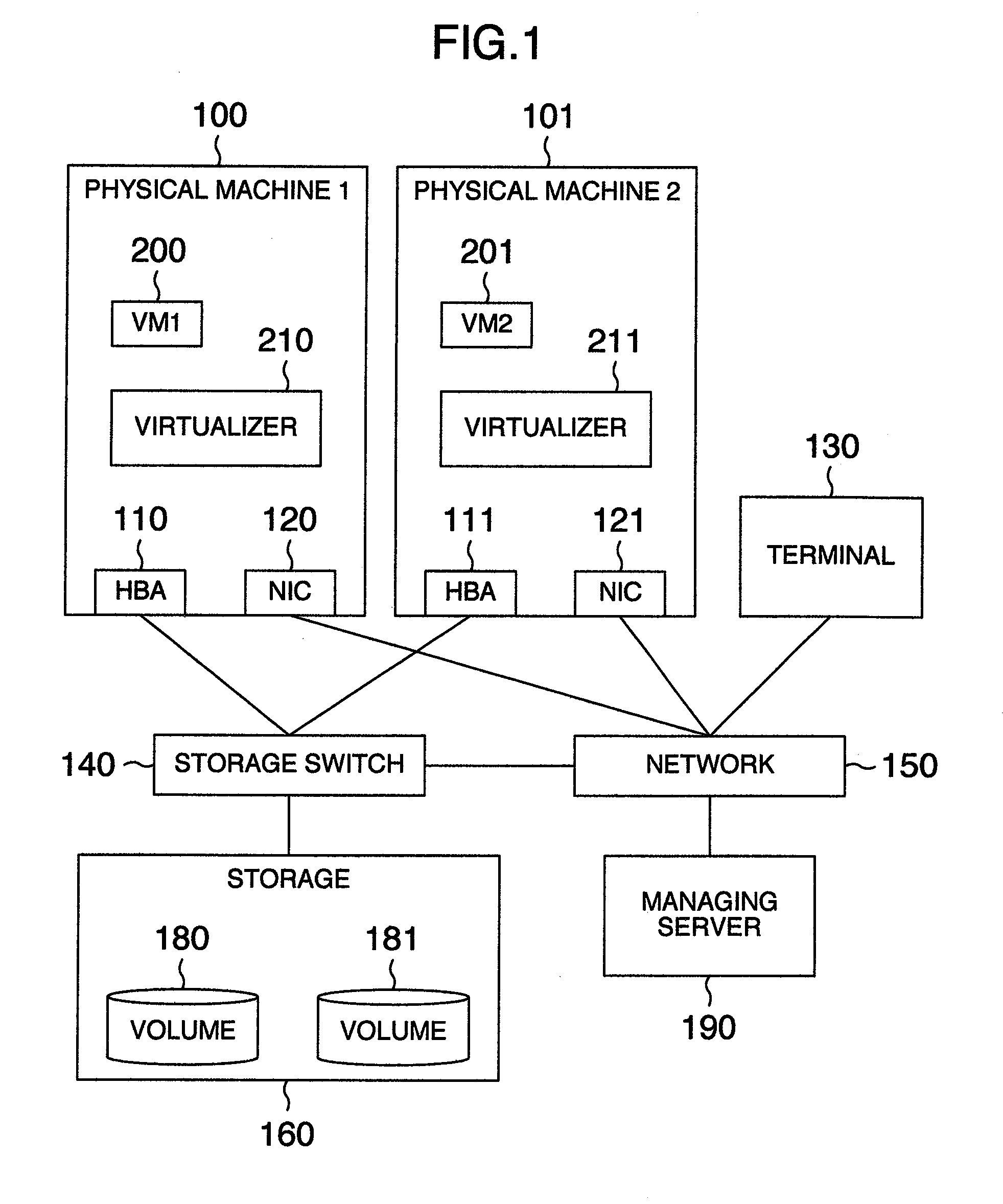
[0040]FIG. 1 shows a configuration of a computer system in the first embodiment of the present invention.

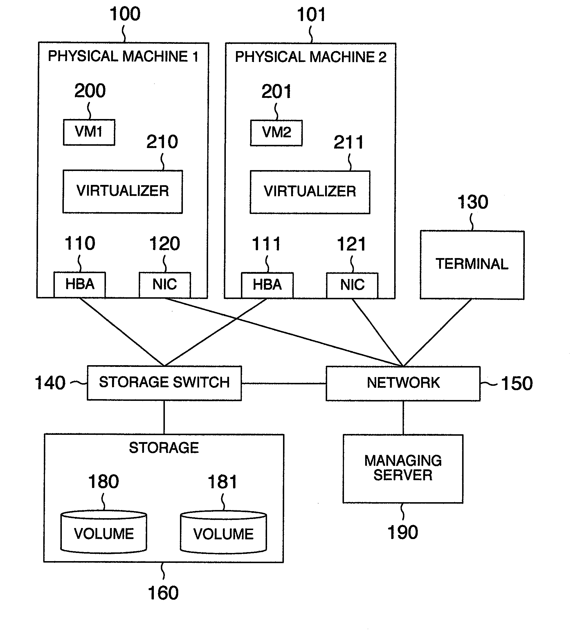
[0041]The computer system of FIG. 1 includes a physical machine 1 (100), a physical machine 2 (101), and a storage 160 as well as a storage switch 140 and a network 150, which establish connections between these constituent components. The network 150 is connected to a terminal 130 to conduct various setting operations for the computer system.

[0042]The physical machine 1 (100) is linked via a fibre-channel Host Bus Adapter (HBA) 110 to the storage switch 140 and is connected via a Network Interface Card (MC) 120 to the network 150. Similarly, the ph...

embodiment 2

[0119]In the second embodiment, the physical machine 100 of the first embodiment further includes a migration destination candidate table 600 shown in FIG. 6. In the computer system of the second embodiment, even if the migration-destination machine is not designated to migrate a virtual machine, the virtualizer 210 migrates the virtual machine to a second physical machine.

[0120]In step 810 of the migration control procedure described in conjunction with FIG. 8, if the indication of the migration-destination machine is absent (missing), the virutalizer 210 selects from the migration destination candidate table 600 a physical machine as the migration destination by use of an address of a virtualizer beforehand registered to the migration destination candidate table 600.

[0121]If there exist a plurality of candidate physical machines, the virutalizer 210 repeatedly issues an associated enquiry to the virtualizer 210 of each physical machine registered to the migration destination candi...

embodiment 3

[0123]The third embodiment is a computer system in which the physical machine 100 of the first embodiment includes migration destination grant information 700 shown in FIG. 7 to prevent migration of a virtual machine.

[0124]If it is required to sustain performance of a virtual machine running on the physical machine 100, VM migration destination prevention information is registered to the migration destination grant information 700 in advance.

[0125]In step 835 of the migration control procedure described in conjunction with FIG. 8, the information items of the migration destination grant information 700 are examined to determine whether or not it is possible to create a migration-destination virtual machine in the migration-destination machine. If the VM migration destination prevention information has been registered to the migration destination grant information 700, a message “VM migration is not possible” is sent to the migration-source machine.

[0126]Through the processing descri...


PUM


Abstract

In a system including a plurality of physical machines to execute virtual machines (VM1, VM2), migration virtual machine information and definition information are saved in a physical machine executing a virtual machine (VM1) to be migrated and a storage of a physical machine as a migration destination. During the migration of the virtual machine, machine identification information of a migration partner, unique information assigned to the virtual machine, and information indicating whether the physical machine executing the processing is a migration-source or migration-destination physical machine are saved in a migration information storage area. A migration recovery section examines information stored in a definition information storage area and a migration information storage area to determine a recovery procedure to restore the virtual machine.

Description

INCORPORATION BY REFERENCE[0001]The present application claims priority from Japanese application JP2009-274050 filed on Dec. 2, 2009, the content of which is hereby incorporated by reference into this application.BACKGROUND OF THE INVENTION[0002]The present invention relates to a technique for use with a system including a plurality of physical machines (real machines) capable of executing virtual machines, and in particular, to a method of migrating a virtual machine from a first physical machine to a second physical machine, a computer using the method, a virtualizer using the method, and a computer system using the method.[0003]According to the virtual technique, it is possible to increase utilization efficiency of hardware resources such as processors, memories, and input and output units. It is also possible to change allocation of such resources to collect a plurality of jobs or applications on one physical machine. Additionally, the virtual technique realizes a function in w...

Claims


Application Information

Patent Timeline
IPC IPC(8): G06F9/455
CPCG06F9/455G06F9/4856G06F2009/4557
Inventor IKEGAYA, NAOKOSEKIGUCHI, TOMOKI
Owner HITACHI LTD
Learn More