
Sensor system for ascertaining a torque and for index detection

Active Publication Date: 2011-06-02
ROBERT BOSCH GMBH
View PDF3 Cites 40 Cited by
  • Summary
  • Abstract
  • Description
  • Claims
  • Application Information

AI Technical Summary

Benefits of technology

[0016]According to the present invention, the position of the index magnet is thus not implemented with the aid of an additional mechanical or contactless switch which is used exclusively for the index function, but rather with the aid of a further magnetic field-sensitive sensor element which supplies a measuring signal even if the shaft equipped with the flux ring unit is not in the angle position defined by the index magnet. This additional measuring signal supplies redundant information for ascertaining the torque and thus contributes to the reliability and availability of the torque detection system. The concept of the index function according to the present invention may also very easily be structurally integrated into a torque sensor system, forming the basis for the present invention. In contrast to the contactlessly operating switching IC known from the related art, the further sensor element may be situated together with the at least one first sensor element on the front of a common printed circuit board in the sensor unit. No special support elements are necessary for this purpose.
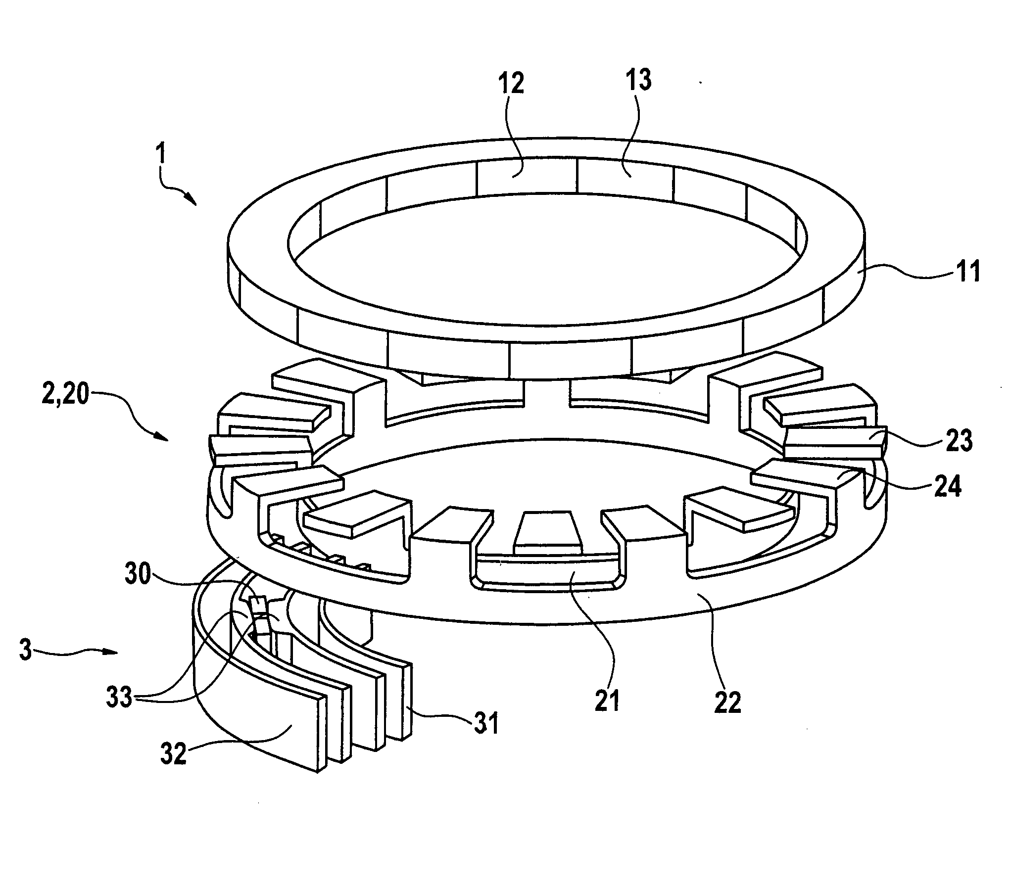
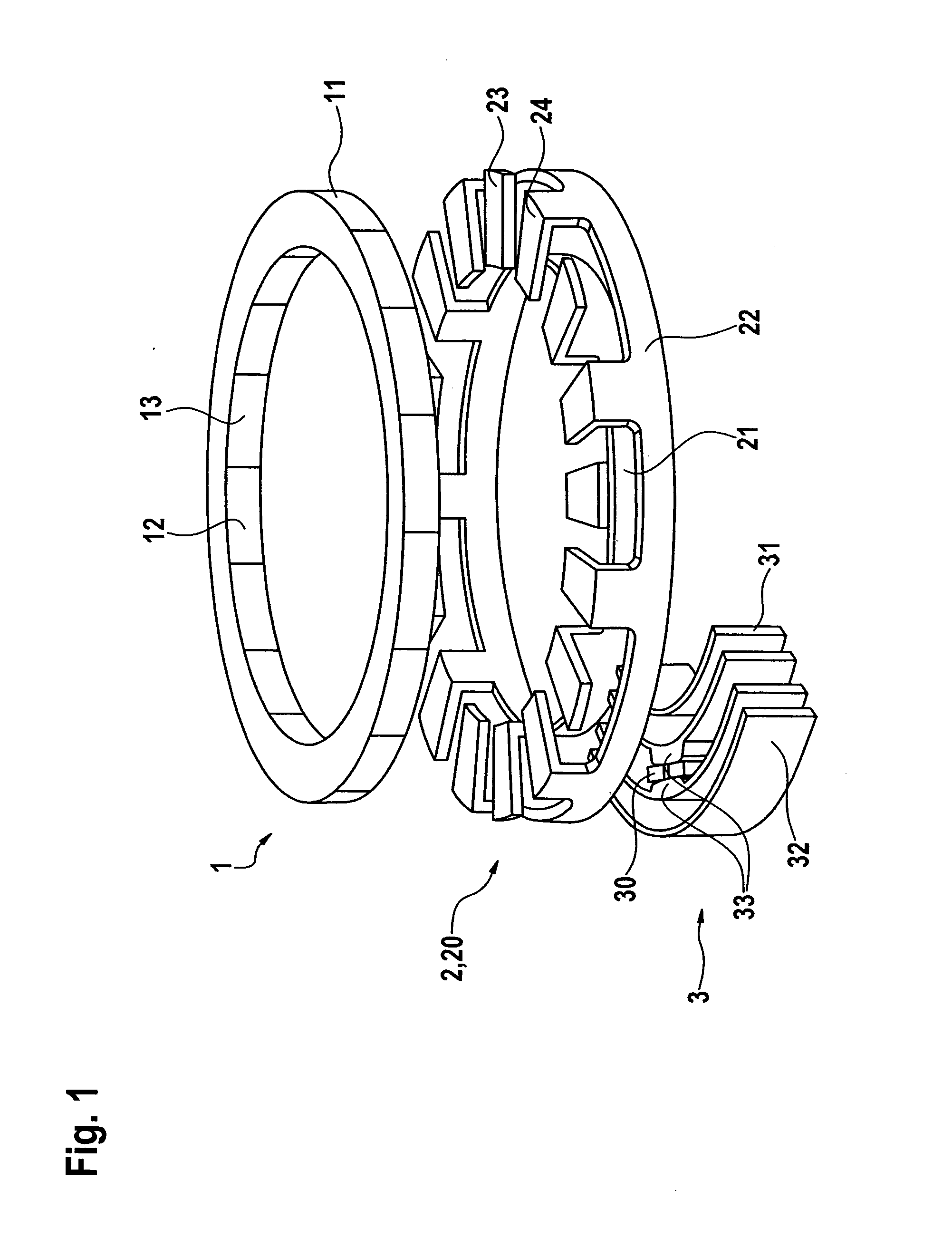
[0019]In an example embodiment of the sensor system according to the present invention, the sensor unit includes at least one magnetic flux-collecting element for each flux ring of the flux ring system, the magnetic flux-collecting elements being situated adjacent to each other. The two sensor elements are then situated in the area of the magnetic flux-collecting elements. The magnetic flux is selectively supplied to the two sensor elements in this manner. The quality of signal detection may be substantially increased thereby. To support the index function, the magnetic flux-collecting elements and the index magnet may also be designed in such a way that the influence of the index magnet on the magnetic flux in the flux ring system is essentially sensed only if the index magnet is located in the area of the magnetic flux-collecting elements. Otherwise, the influence of the index magnet on the sensor signal is so weak that is negligible.
[0021]Supplying the magnetic flux to the sensor elements may be easily further improved in this case by the fact that the outer ring section of the magnetic flux-collecting element of the inner flux ring and the inner ring section of the magnetic flux-collecting element of the outer flux ring have special formations for the sensor elements to minimize the air gap between these ring sections and the collecting elements. The formations may also be designed in such a way that the sensor elements are in physical contact with the ring sections.

Problems solved by technology

However, the structure of the known sensor system having a magnetically implemented index function is relatively complex, in particular where the position of the index magnet and the mounting of the switching IC are concerned.

Method used


Image

  • Sensor system for ascertaining a torque and for index detection
  • Sensor system for ascertaining a torque and for index detection
  • Sensor system for ascertaining a torque and for index detection

Examples


Embodiment Construction

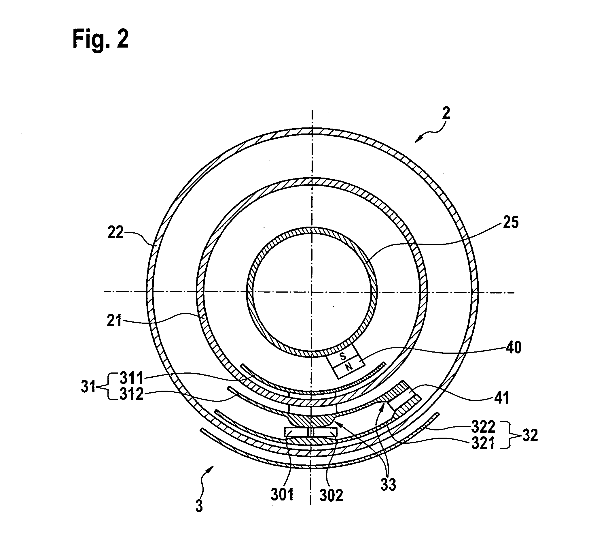
[0026]Sensor system 100 illustrated in FIG. 2 is structured similarly to the sensor system illustrated inFIG. 1, but the present invention additionally has index detection means, namely an index magnet 40 and an additional magnetic field-sensitive sensor element 41. The present invention requires specific positioning of these components within sensor system 100, which is illustrated particularly effectively by the schematic sectional representation in FIG. 2.

[0027]The sectional plane is oriented perpendicularly to the shaft axis and passes through flux ring unit 2, which includes inner flux ring 21 and outer flux ring 22. The two flux rings 21 and 22 are mounted concentrically to the shaft axis and parallel to the magnetic pole wheel of the magnetic unit, which is not illustrated here, since it is situated above the section plane. As shown in FIG. 1, inner flux ring 21 is provided with ferromagnetic teeth which face outward from the shaft in the radial direction, while outer flux ri...


PUM


Abstract

A torque sensor system having an index function and ascertaining a torque between an input shaft and an output shaft connected to each other via a torsion bar, includes: a magnetic unit having a magnetic pole wheel for generating a magnetic field, the magnetic unit being rigidly connected to one of the two shafts; a flux ring unit having a flux ring system for converting and conducting the magnetic flux generated by the magnetic unit, the flux ring unit being rigidly connected to the other shaft; and a sensor unit having at least one first magnetic field-sensitive sensor element for sensing changes in the magnetic flux through the flux ring system, the sensor unit being mounted in a stationary manner relative to the flux ring unit. The index function is implemented with the aid of an index magnet and a further magnetic field-sensitive sensor element.

Description

BACKGROUND OF THE INVENTION[0001]1. Field of the Invention[0002]The present invention relates to a sensor system for ascertaining a torque between an input shaft and an output shaft which are connected to each other via a torsion bar.[0003]2. Description of the Related Art[0004]For this purpose, the sensor system includes a magnetic unit having a magnetic pole wheel for generating a magnetic field, the magnetic unit being rigidly connected to one of the two shafts; a flux ring unit having a flux ring system for converting and conducting the magnetic flux generated by the magnetic unit, the flux ring unit being rigidly connected to the other shaft; and a sensor unit having at least one first magnetic field-sensitive sensor element for sensing changes in the magnetic flux through the flux ring system, the sensor unit being mounted in a stationary manner in relation to the flux ring unit.[0005]A sensor system of this type is described in published German patent application document DE ...

Claims


Application Information

Patent Timeline
IPC IPC(8): G01L3/02
CPCG01L3/104B62D6/10B62D15/0245
Inventor BEHRENS, HOLGER
Owner ROBERT BOSCH GMBH
Learn More