Eureka AIR delivers breakthrough ideas for toughest innovation challenges, trusted by R&D personnel around the world.

Ridge Vent with Powered Forced Air Ventilation

a forced air ventilation and ridge vent technology, applied in ventilation systems, lighting and heating apparatuses, heating types, etc., can solve the problems of insufficient attic humidity, inability to drive robust ventilation, and inability to meet the needs of attic ventilation, so as to achieve the effect of improving ventilation

Active Publication Date: 2011-05-26
BMIC LLC
View PDF27 Cites 25 Cited by
  • Summary
  • Abstract
  • Description
  • Claims
  • Application Information

AI Technical Summary

Benefits of technology

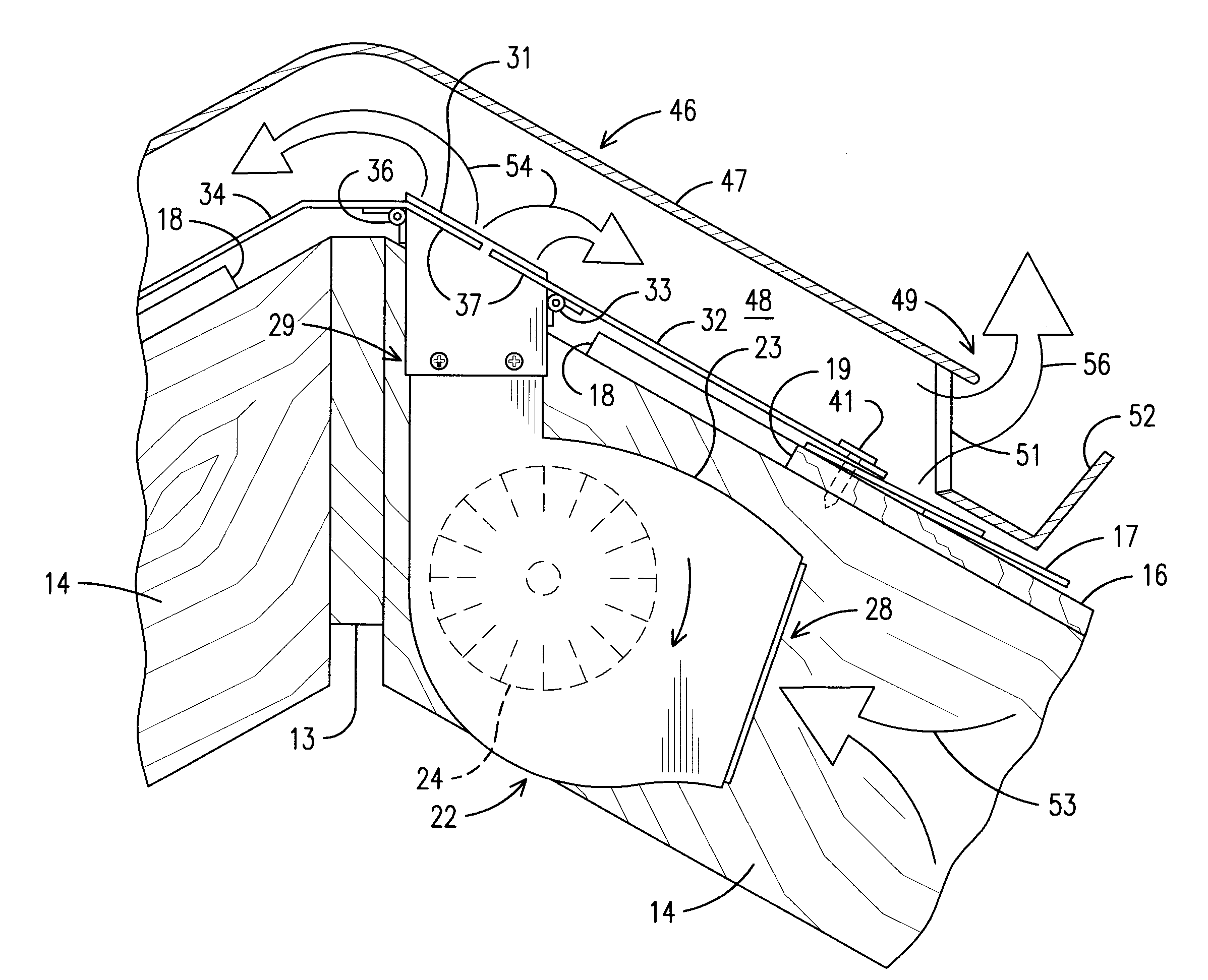
With the blower or blowers installed, the ridge vent is installed along the ridge of the roof in the conventional manner so that it covers the ridge slot and also covers the blower baffles at the location of each blower. In the preferred embodiment, the ridge vent is of the panel type with edge vents so that the space between the ridge vent panel and the roof forms a vent path for attic air to flow to the edges of the panel where it is vented to ambience. Operation of a blower enhances ventilation by forcibly drawing in attic air through the blower inlet within the attic and forcibly exhausting the air through the blower outlet into the space between the roof and the ridge vent panel. This forced air, then, is forced to the vents at the edges of the panel, where it is ejected into the atmosphere. The baffles on each side of the blower outlet help insure that the exhausted attic air does not simply circulate back into the attic through the ridge slot or the blower opening.

Problems solved by technology

For example, the temperature of the attic air may be too low to drive robust ventilation, but the humidity in the attic may be undesirably high such that attic ventilation is needed anyway.
However, most have inherent shortcomings such as expense, difficulty of installation, requirement for a specially designed ridge vent, or inapplicability to roofs with a central ridge beam along the ridge.

Method used


Image

  • Ridge Vent with Powered Forced Air Ventilation
  • Ridge Vent with Powered Forced Air Ventilation
  • Ridge Vent with Powered Forced Air Ventilation

Examples


Embodiment Construction

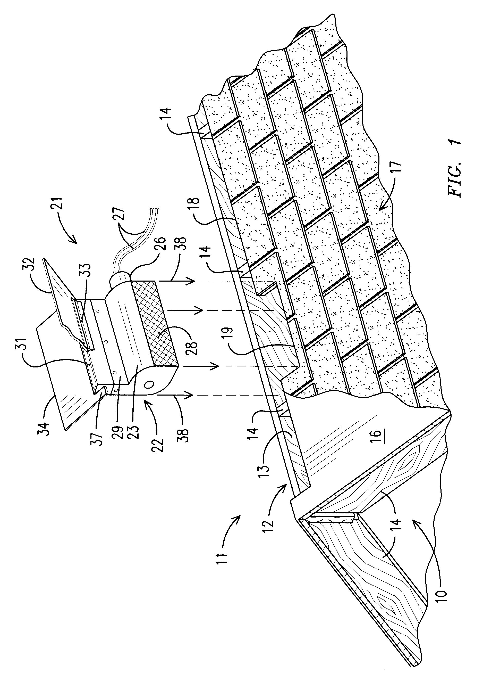
Referring now in more detail to the drawing figures, wherein like reference numerals designate like parts throughout the several views, FIG. 1 illustrates an embodiment of a blower and its installation along a roof ridge. The roof 11 overlies and bounds an attic space 10 of a dwelling or other structure. The roof 11 is of the gable design having a roof ridge 12 along which a wooden ridge beam 13 extends. A plurality of roof rafters 14 are secured to the ridge beam 13 and extend downwardly at an angle on either side of the ridge. The roof rafters typically are spaced apart 16 inches on center, but may have a different spacing such as, for instance, 24 inches on center. The rafters 14 support a roof deck 16 upon which underlayment and shingles 17 are secured.

The roof 11 in FIG. 1 is prepared for installation of ridge vents along the ridge 12 of the roof. More specifically, a ridge slot 18 has been cut in the roof deck on either side of the ridge beam 13 through which air within the at...


PUM


Abstract

A ridge vent with powered forced air ventilation includes a ridge vent that is configured to be installed along the ridge of a roof covering an elongated ridge slot on either side of a ridge beam of the roof. Hot air from the attic below escapes by convection through the ridge slot and is expelled to ambient atmosphere through the ridge vent. A blower is mounted in a blower opening formed at a predetermined location along the ridge vent on one side of the ridge beam. The blower includes a blower housing forming an inlet within the attic and an outlet oriented to force air upwardly through the vent slot to be expelled through the ridge vent. A pair of baffles are hingedly secured to the housing adjacent its outlet and can be hinged up for dropping the blower through the blower opening during installation, and then hinged down and attached to a roof deck covering the blower opening and a portion of the ridge slot on the other side of the ridge beam. The baffles secure the blower and help to isolate its outlet from the attic space below. An impeller is disposed in the housing and is driven by an electric motor, which may be driven by electricity from a solar panel, electricity from a household electrical service, or both depending upon availability of sunlight and other conditions.

Description

TECHNICAL FIELDThis disclosure relates generally to attic ventilation and more specifically to a ridge vent system for gable roofs that includes powered forced air ventilation.BACKGROUNDAttic ventilation has improved significantly over time. Many types of attic vents are used for attic ventilation such as, for instance, attic fans, attic vents, and gable vents. One type of attic vent that has proven successful, particularly for gable roofs with one or more roof ridges, is the ridge vent. Ridge vents are available in many configurations. Generally, however, a ridge vent covers an open ridge slot along the apex or ridge of a gable roof. The ridge vent is configured to define a flow path for hot and / or humid attic air to exit the attic through the ridge slot and ridge vent, while preventing rainwater, snow, and insects from entering the attic. Ridge vents may be configured, for example, as an open weave mat material that is applied over the ridge slot and covered with ridge cap shingle...

Claims


Application Information

Patent Timeline
IPC IPC(8): F24F7/06E04D13/17
CPCE04D13/174F24F7/02F24F7/025
Inventor RAILKAR, SUDHIRZARATE, WALTERCHICH, ADEM
Owner BMIC LLC
Why Eureka
Eureka Blog
Learn More