
Pairing of components in a direct current distributed power generation system

a power generation system and component technology, applied in the field of power generation systems, can solve the problem of limited current output of photovoltaic modules

Active Publication Date: 2011-05-26
SOLAREDGE TECH LTD
View PDF100 Cites 179 Cited by
  • Summary
  • Abstract
  • Description
  • Claims
  • Application Information

AI Technical Summary

Benefits of technology

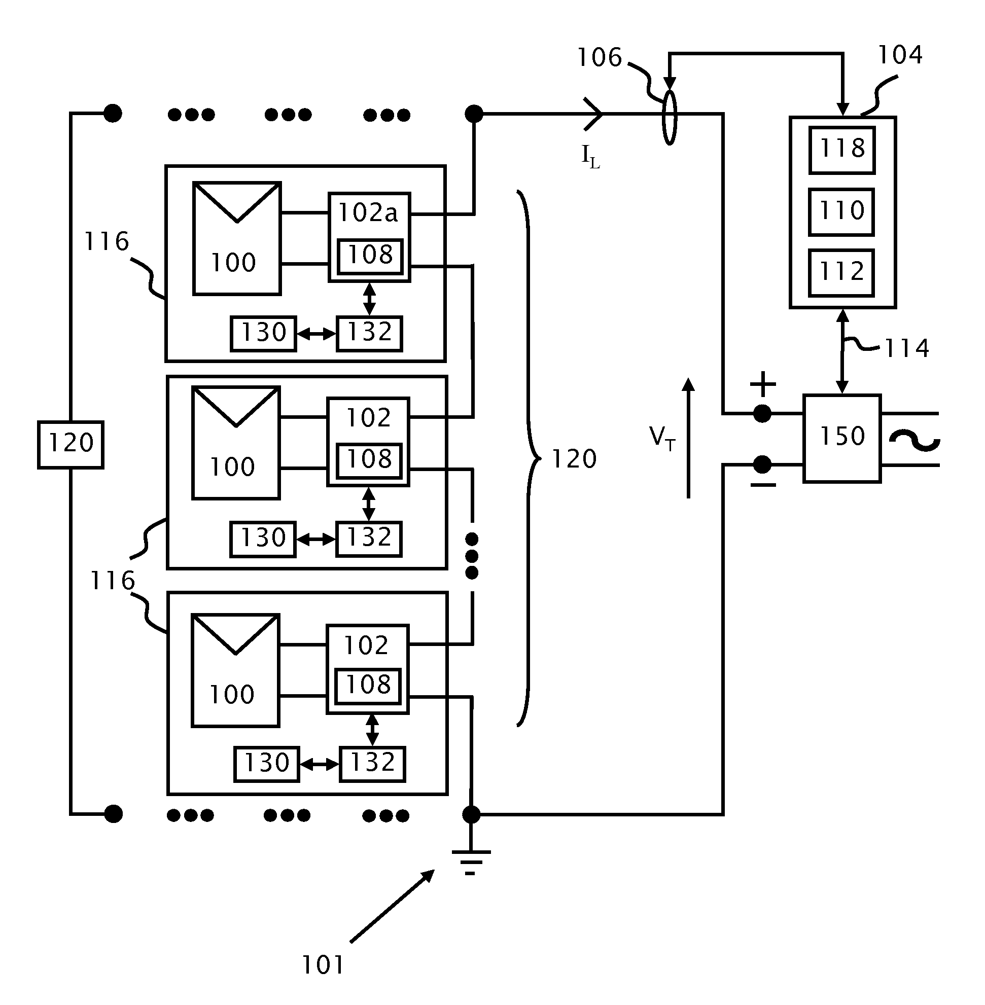
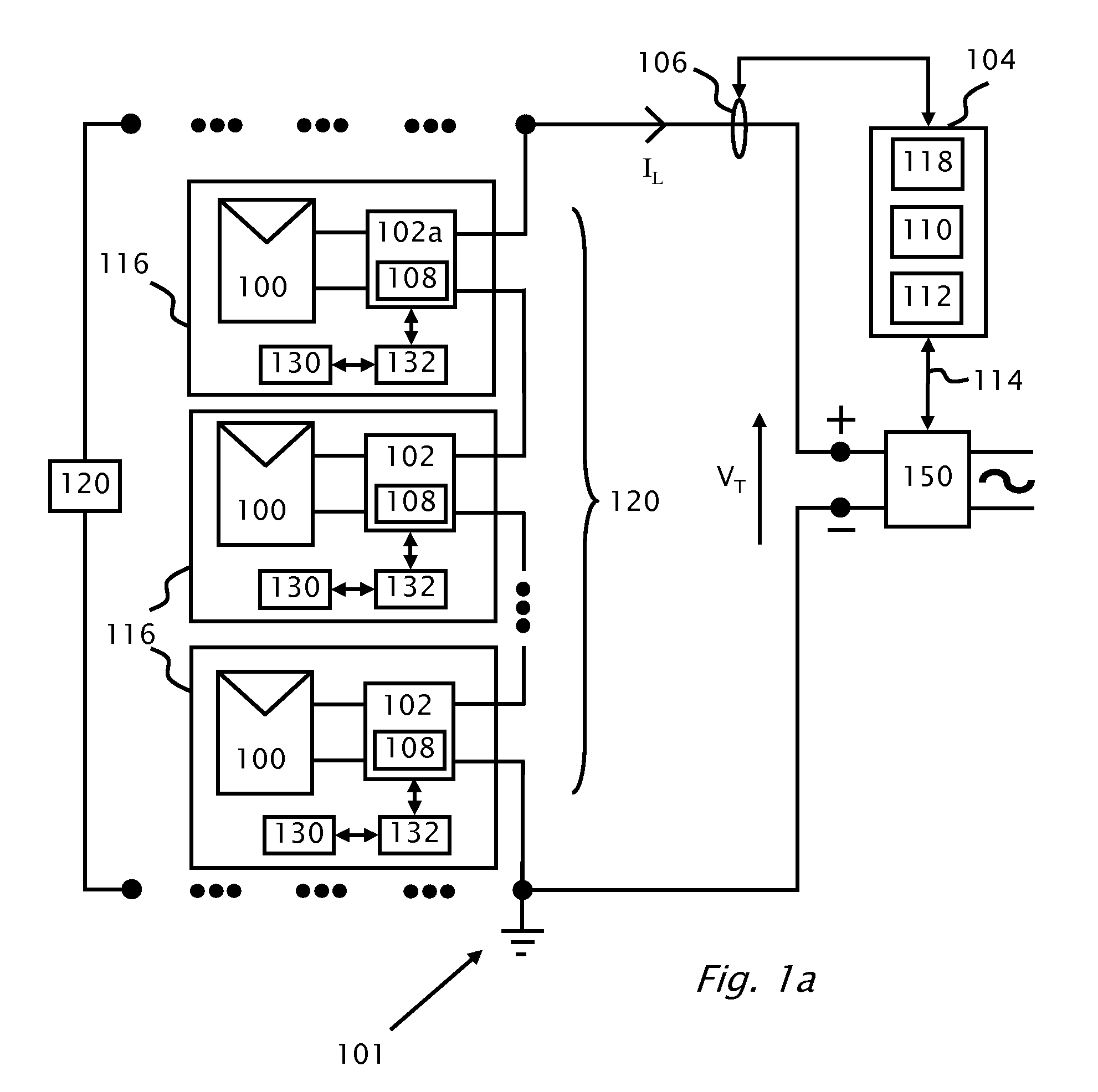
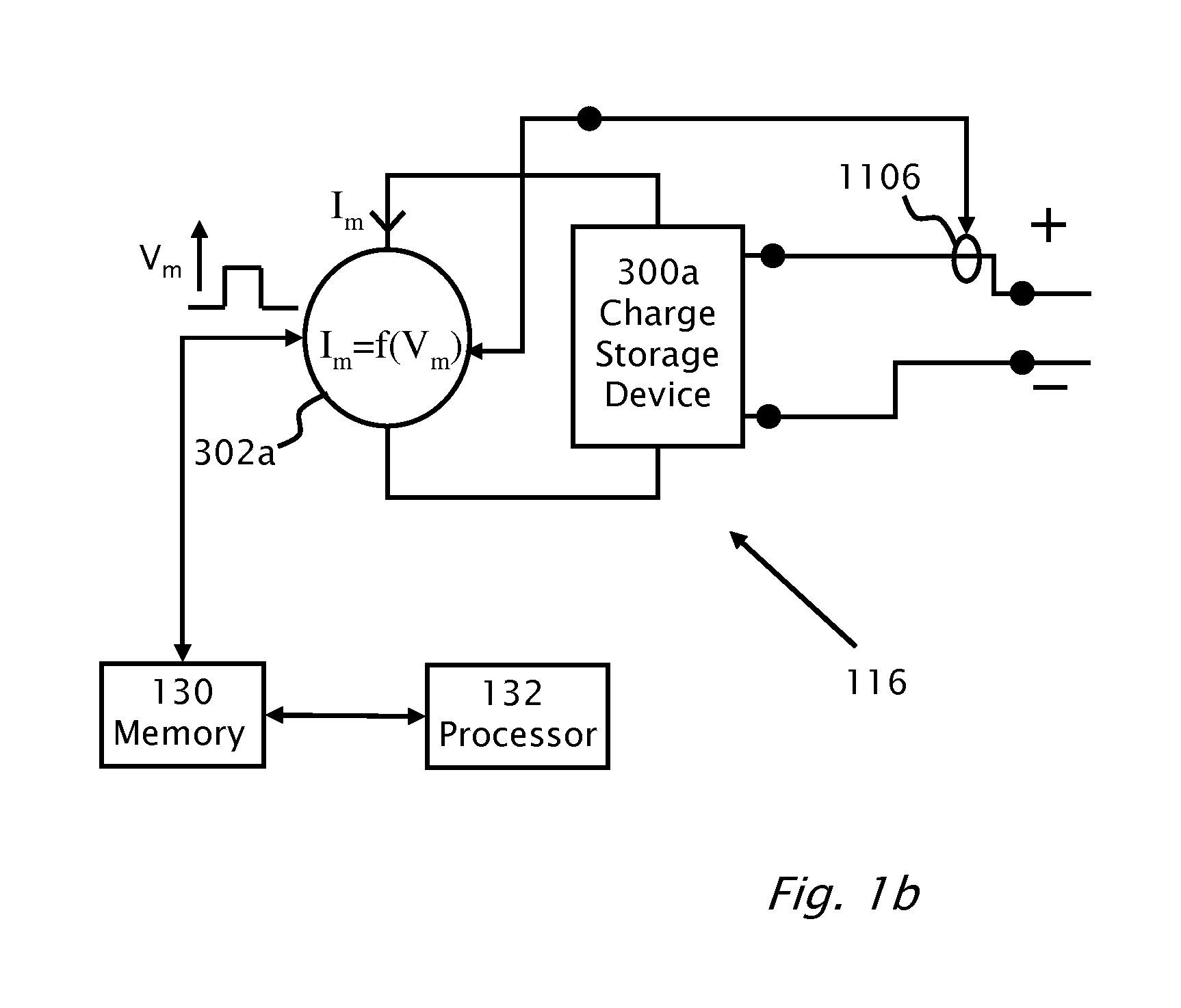
[0020]According to the present invention there is provided a method of signaling between a photovoltaic module and an inverter module. The inverter module is connected to the photovoltaic module. In an initial mode of operation an initial code is modulated to produce an initial signal. The initial signal is transmitted from the inverter module to the photovoltaic module. The initial signal is received by the photovoltaic module. The operating mode is then changed to a normal mode of power conversion, and during the normal mode of operation a control signal is transmitted from the inverter to the photovoltaic module. A control code is demodulated and received from the control signal. The control code is compared with the initial code producing a comparison. The control command of the control signal is validated as a valid control command from the inverter module with the control command only acted upon when the comp

Problems solved by technology

Current output of photovoltaic modules may be limited during the initial mode of operation.

Method used


Image

  • Pairing of components in a direct current distributed power generation system
  • Pairing of components in a direct current distributed power generation system
  • Pairing of components in a direct current distributed power generation system

Examples


Embodiment Construction

[0029]Reference will now be made in detail to embodiments of the present invention, examples of which are illustrated in the accompanying drawings, wherein like reference numerals refer to the like elements throughout. The embodiments are described below to explain the present invention by referring to the figures.

[0030]It should be noted, that although the discussion herein relates primarily to methods in photovoltaic systems, the present invention may, by non-limiting example, alternatively be configured as well using other distributed power systems including (but not limited to) wind turbines, hydro-turbines, fuel cells, storage systems such as battery, super-conducting flywheel, and capacitors, and mechanical devices including conventional and variable speed diesel engines, Stirling engines, gas turbines, and micro-turbines.

[0031]It should be noted that although embodiments of the present invention are described in terms of an inverter as a load, the present invention may be app...


PUM


Abstract

A method of signaling between a photovoltaic module and an inverter module. The inverter module is connected to the photovoltaic module. In an initial mode of operation an initial code is modulated thereby producing an initial signal. The initial signal is transmitted from the inverter module to the photovoltaic module. The initial signal is received by the photovoltaic module. The operating mode is then changed to a normal mode of power conversion, and during the normal mode of operation a control signal is transmitted from the inverter to the photovoltaic module. A control code is demodulated and received from the control signal. The control code is compared with the initial code producing a comparison. The control command of the control signal is validated as a valid control command from the inverter module with the control command only acted upon when the comparison is a positive comparison.

Description

CROSS REFERENCE TO RELATED APPLICATIONS[0001]The present application is a continuation-in-part of pending U.S. patent application Ser. No. 12 / 329,525 filed on Dec. 5, 2008 by the present inventors the disclosure of which is included herein by reference. The present application claims priority from pending U.S. patent application Ser. No. 12 / 788,066 filed on May 26, 2010.FIELD AND BACKGROUND[0002]1. Field[0003]The present invention relates to power generation systems, and specifically to a system and method for reducing crosstalk while signaling between the components in direct current distributed power generation systems.[0004]2. Related Art[0005]A photovoltaic power generation system may incorporate one or more photovoltaic panels with optional electronic modules attached thereto. An inverter connects to the photovoltaic panels or electronic modules. Power output from the photovoltaic panels or electronic modules is direct current (DC) power. The electronic modules may perform dire...

Claims


Application Information

Patent Timeline
IPC IPC(8): H02J1/10
CPCH01L31/02021H02J1/102H02J3/382H02J3/383H02J3/386H02J7/35G03B23/02Y02E10/566Y02E10/763H02J3/381H02J3/387H02J1/10Y02E10/563H02S50/00G06Q30/0242G06Q30/0273H02J2300/10H02J2300/30H02J2300/28H02J2300/20H02J2300/24Y02E10/56Y02E10/76H02S40/34
Inventor SELLA, GUYADEST, MEIRHANDELSMAN, LIORGALIN, YOAVFISHELOV, AMIRGAZIT, MEIRYOSKOVITCH, ILANBINDER, YARON
Owner SOLAREDGE TECH LTD
Learn More