Teaching line correcting apparatus, teaching line correcting method, and program thereof

a teaching line and correcting technology, applied in the field of teaching line correcting apparatus, teaching line correcting method, and the program thereof, can solve the problems of inaccurate correction of teaching data, inability to correct teaching data, and tendency to suffer errors, so as to reduce errors

Active Publication Date: 2011-05-19
HONDA MOTOR CO LTD
View PDF10 Cites 8 Cited by
  • Summary
  • Abstract
  • Description
  • Claims
  • Application Information

AI Technical Summary

Benefits of technology

[0007]It is an object of the present invention to provide a teaching line correcting apparatus, a teaching line correcting method, and a program for correcting teaching data (teaching lines) accurately while reducing errors that occur when the correlation of reference regions is different, and also for correcting teaching data even if one of the positions of the reference regions cannot be detected.
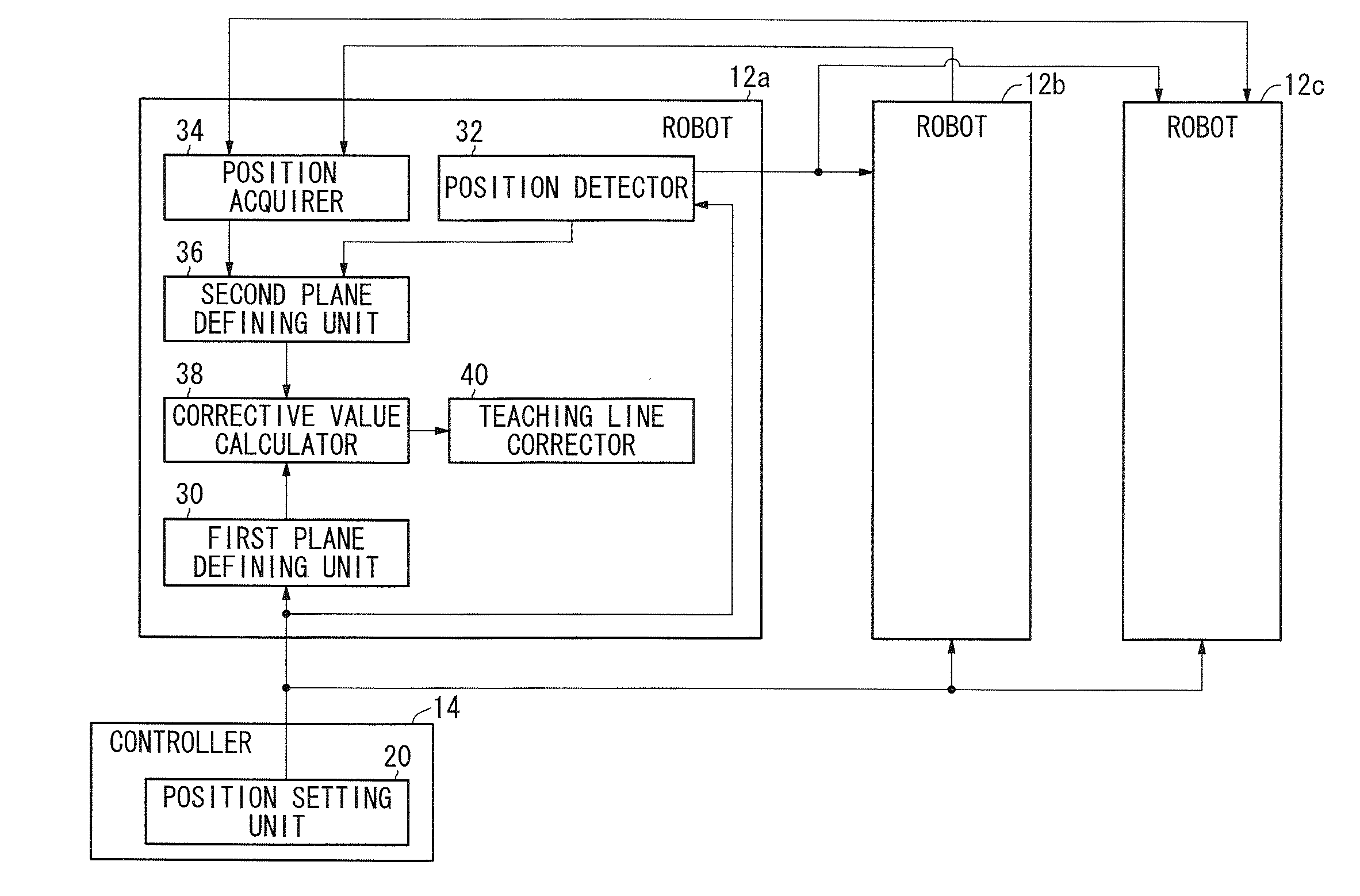
[0016]According to the present invention, the first plane and the second plane include lines passing through the starting operation points of the robot or the positions of the first reference regions within given ranges from the starting operation points, and the ending operation points of the robot or the positions of the second reference regions within given ranges from the ending operation points, and which are determined by the detected positions of the third reference regions. A corrective value is calculated for equalizing the reference position (a) of the first reference region as the origin to the detected position (a′) of the second reference region as the origin, and for equalizing the first plane to the second plane. Reference coordinates where operating points are taught are corrected according to the calculated corrective value. Therefore, even if the correlation of the reference regions on the workpiece is different due to error, the effect that the error has on the correction of the teaching line can be reduced. The correction accuracy and the stability of the correction accuracy thus are increased.
[0017]If the position of any one of the first reference region, the second reference region, or the third reference region cannot be detected, then since the corrective value is calculated from the first plane and the second plane by moving the origin to the reference region, which is closest to the first reference region, and using the undetected reference region to determine an angle of the second plane, the teaching line can be corrected even though the position of any one of the first reference region, the second reference region, and the third reference region is not detected. Since the teaching line, after being corrected, can absorb the distance that the workpiece has moved on the first plane, the robot can apply the sealer more accurately than if the teaching line were not corrected.
[0018]If the workpiece comprises an automobile body made up of a plurality of panels, then the position setting unit sets two of the first reference position, the second reference position, and the third reference position on one of the panels, while setting the remaining reference position on another one of the panels. In this manner, when a teaching line, which is set on a desired one of the panels, is corrected, the effect that the accuracy with which the panels are assembled together has on the correction of the teaching line is reduced.

Problems solved by technology

If the positions of the corresponding points P are different from predetermined positions for various reasons such as machine errors, then the correlation of the points P from the origin 0 tends to suffer from errors, and such teaching data cannot be corrected accurately.
Further, if any one of the positions of the points P (reference regions) cannot be detected, then the teaching data cannot be corrected.

Method used


Image

  • Teaching line correcting apparatus, teaching line correcting method, and program thereof
  • Teaching line correcting apparatus, teaching line correcting method, and program thereof
  • Teaching line correcting apparatus, teaching line correcting method, and program thereof

Examples


Embodiment Construction

[0026]A teaching line correcting apparatus according to a preferred embodiment of the present invention will be described in detail below with reference to the accompanying drawings.

[0027]FIG. 1 is a perspective view of a teaching line correcting apparatus 10 according to an embodiment of the present invention. As shown in FIG. 1, the teaching line correcting apparatus 10 comprises at least three robots 12a, 12b, 12c, and a controller 14 for controlling the robots 12a, 12b, 12c. Each of the robots 12a, 12b, 12c includes an articulated arm 16 having multiple degrees of freedom for three-dimensional movement in any of desired directions. Two sealer guns 18 are carried on a distal end of the articulated arm 16 for applying a sealer to a workpiece 100 such as an automobile body, for example. A position detector 32 also is carried thereon for detecting the spatial positions of reference regions on the workpiece 100. The sealer guns 18 are used selectively depending on the type of sealer ...


PUM


Abstract

A teaching line correcting apparatus defines a first plane, which is determined by a first reference position of a preset first reference region, a second reference position of a preset second reference region, and a third reference position of a preset third reference region, defines a second plane, which is determined by a detected position of the first reference region, a detected position of the second reference region, and a detected position of the third reference region, calculates a corrective value for equalizing the first reference region to an origin, equalizing the first reference position of the first reference region as the origin to the detected position of the first reference region as the origin, and equalizing the first plane to the second plane, and correcting reference coordinates where operating points are taught based on the calculated corrective value.

Description

CROSS-REFERENCE TO RELATED APPLICATION[0001]This application is based upon and claims the benefit of priority from Japanese Patent Application No. 2009-262706 filed on Nov. 18, 2009, of which the contents are incorporated herein by reference.BACKGROUND OF THE INVENTION[0002]1. Field of the Invention[0003]The present invention relates to a teaching line correcting apparatus, a teaching line correcting method, and a program thereof. More particularly, the present invention concerns a teaching line correcting apparatus, a teaching line correcting method, and a program for correcting with high accuracy a teaching line for an industrial robot that works on a workpiece, such as for applying a sealer to the workpiece, welding the workpiece, etc.[0004]2. Description of the Related Art[0005]In the art of industrial robot teaching, there has been proposed a technology for measuring and acquiring three-dimensional coordinate data, which are representative of positions of operating points of an...

Claims


Application Information

Patent Timeline
Patent Type & Authority Applications(United States)
IPC IPC(8): G05B19/04
CPCG05B2219/40385B25J9/1656
Inventor HAYAMA, HIRONOBUMURAKAMI, SHINYAHARIYA, YUTAKAETO, NAOKITAKEBE, MASASHI
Owner HONDA MOTOR CO LTD
Why Eureka
Try Eureka