Universal direction medical positioning structure

Inactive Publication Date: 2011-05-19
ACCUMIS
View PDF1 Cites 7 Cited by
  • Summary
  • Abstract
  • Description
  • Claims
  • Application Information

AI Technical Summary

Benefits of technology

[0009]The present invention provides a universal direction medical positioning structure that comprises a positioning unit with a spherical connecting element. The positioning unit can rotate freely to facilitate three-dimensional adjustment and thus eliminate the difficulty in otherwise confronting a plurality of switching heads disclosed in the prior art.
[0010]The present invention provides a universal direction medical positioning structure that uses fewer spherical connecting elements than a conventional universal direction medical positioning structure. The universal direction medical positioning structure is relatively lighter in weight, enables convenient operation, and dispenses with multiple adjustments otherwise required for the conventional universal direction medical positioning structure with a plurality of switching heads.
[0011]The present invention provides a universal direction medical positioning structure which is relatively lighter in weight and therefore unlikely to loosen when held by means of clamping or insertion. Thus, the present invention overcomes the problem that a conventional universal direction medical positioning structure has in loosening during surgery due to its heavier weight, which consists of a plurality of switching heads.
[0015]1. The universal direction medical positioning structure includes the spherical connecting element, the switching head, and the fixing device so as to be lightweight and easy to operate.
[0016]2. The universal direction medical positioning structure is lightweight and thereby unlikely to loosen, thereby enhancing positioning preciseness.

Problems solved by technology

The universal direction medical positioning structure can provide interchangeable clamping-based fixing rod and insertion-based fixing rod, which is unattainable by a conventional universal direction medical positioning structure that provides no alternative to the way of coupling the fixing rod to the switching head.

Method used


Image

  • Universal direction medical positioning structure
  • Universal direction medical positioning structure
  • Universal direction medical positioning structure

Examples


Embodiment Construction

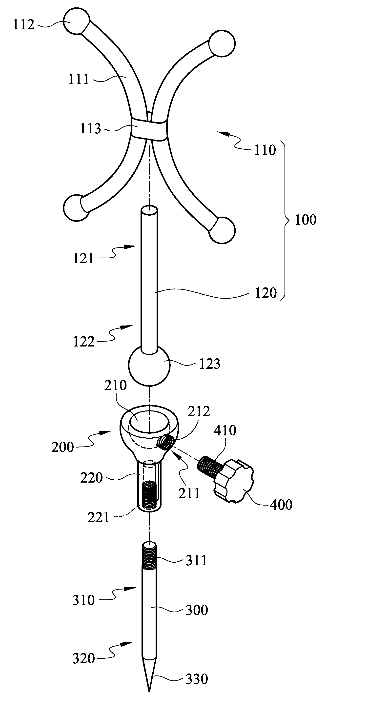
[0029]Please refer to FIG. 1 for an exploded perspective view of a universal direction medical positioning structure in an embodiment according to the present invention. As shown in the drawing, the universal direction medical positioning structure comprises a positioning unit 100, a switching head 200, a fixing rod 300, and a fixing device, wherein the fixing device as shown in FIG. 1 is a first fixing fastener 400, and the first fixing fastener 400 is a screw.

[0030]Referring to FIG. 1, the positioning unit 100 comprises a support 110, a connecting rod 120, and a spherical connecting element 123. The connecting rod 120 has a first end portion 121 and a second end portion 122. The first end portion 121 of the connecting rod 120 is connectable to the support 110. The second end portion 122 of the connecting rod 120 is coupled to the spherical connecting element 123.

[0031]Referring to FIG. 1, the support 110 comprises at least one arm 111, and the arms 111 are connected to a fulcrum 1...


PUM


Abstract

Provided is a universal direction medical positioning structure, including a positioning unit, a switching head, a fixing rod, and a fixing device. The positioning unit includes a support, a connecting rod, and a spherical connecting element. The support and the spherical connecting element are connectable to two ends of the connecting rod, respectively. One end of the switching head is provided therein with a hemispherical cavity for receiving the spherical connecting element, and the other end of the switching head is coupled to the fixing rod. Upon the coupling of the fixing device and the switching head, the spherical connecting element is fixed in position to the hemispherical cavity of the switching head. Hence, the universal direction medical positioning structure is lightweight and easy to operate.

Description

BACKGROUND OF THE INVENTION[0001]1. Technical Field[0002]The present invention relates to universal direction medical positioning structures, and more particularly, to a universal direction medical positioning structure for use in a surgical navigation system.[0003]2. Description of Related Art[0004]As a result of injuries or spinal degeneration, the human spine (including lumbar vertebrae, thoracic vertebrae, and cervical vertebrae) is likely to encounter fracture, intervertebral disk herniation, and spondylolisthesis and thereby suffer pain when spinal nerves inside the spinal canal are compressed. The aforesaid diseases can be cured by conventional surgery that involves, for example, inserting into the human spine a front fixer, a rear fixer, a cage spacer, or an artificial intervertebral disc. In this regard, a surgical navigation system can always assist with the aforesaid surgery so as to render the aforesaid surgery smooth and successful.[0005]Before surgery, a surgical navig...

Claims


Application Information

Patent Timeline
IPC IPC(8): A61B19/00
CPCA61B19/5244A61B2019/5491A61B2019/5483A61B2019/5416A61B2090/3983A61B2090/3916A61B2090/3991A61B34/20
Inventor WU, MING-CHANGHONG, JIA-JYUNTIEN, HUNG-SHENGWU, CHI-BIN
Owner ACCUMIS
Why Eureka
Try Eureka