Printer and printing method for lenticular sheet
a printing method and lenticular sheet technology, applied in the field of lenticular sheet printing and printing methods, can solve the problems of no known technique for 261120 does not disclose the orientation detection of the lenticular sheet in the line printer, and no known technique for the detection and adjustment of the orientation of the lenticular sheet, etc., to achieve good positioning and high precision
- Summary
- Abstract
- Description
- Claims
- Application Information
AI Technical Summary
Benefits of technology
Problems solved by technology
Method used
Image
Examples
2nd embodiment
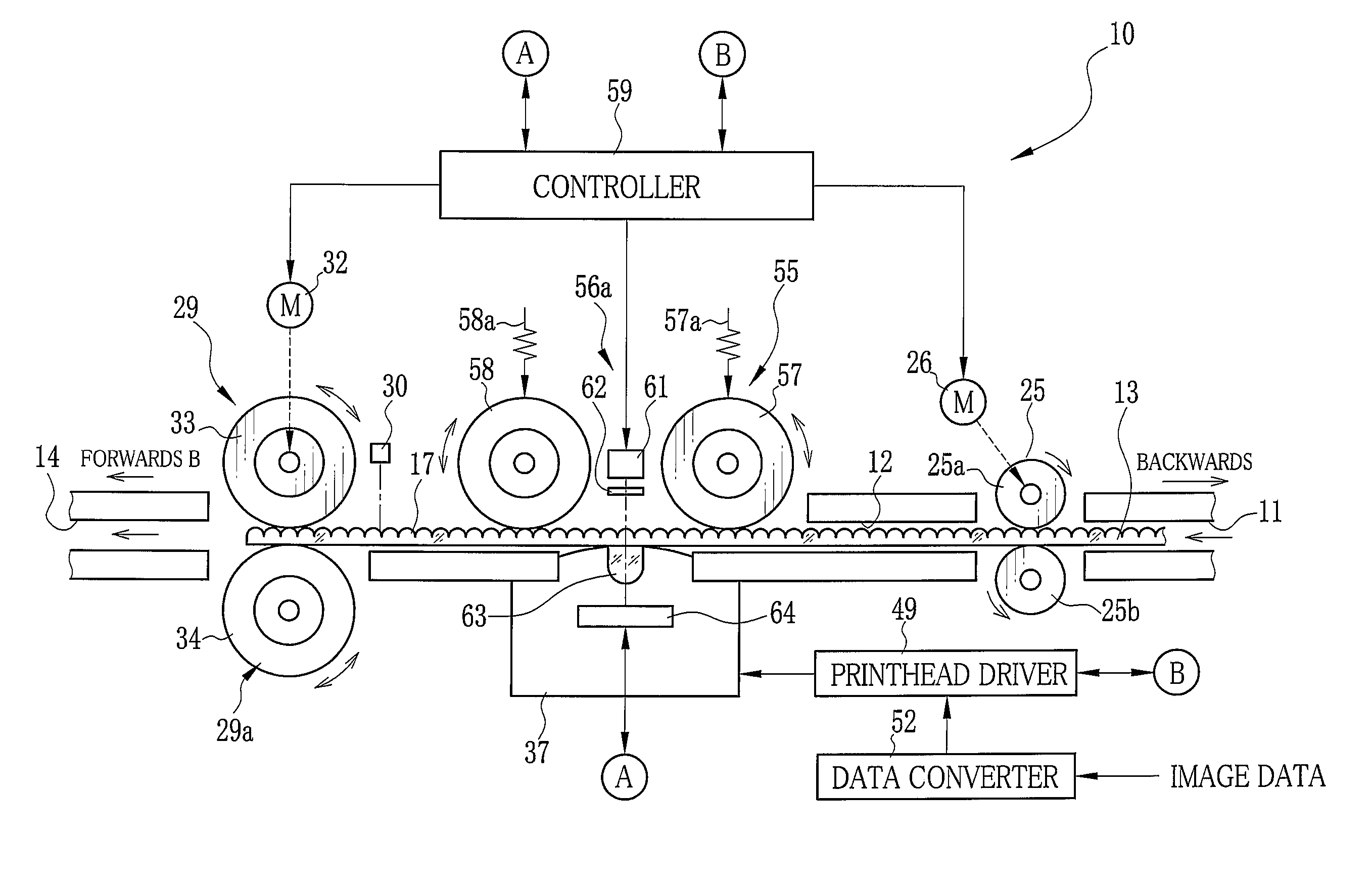
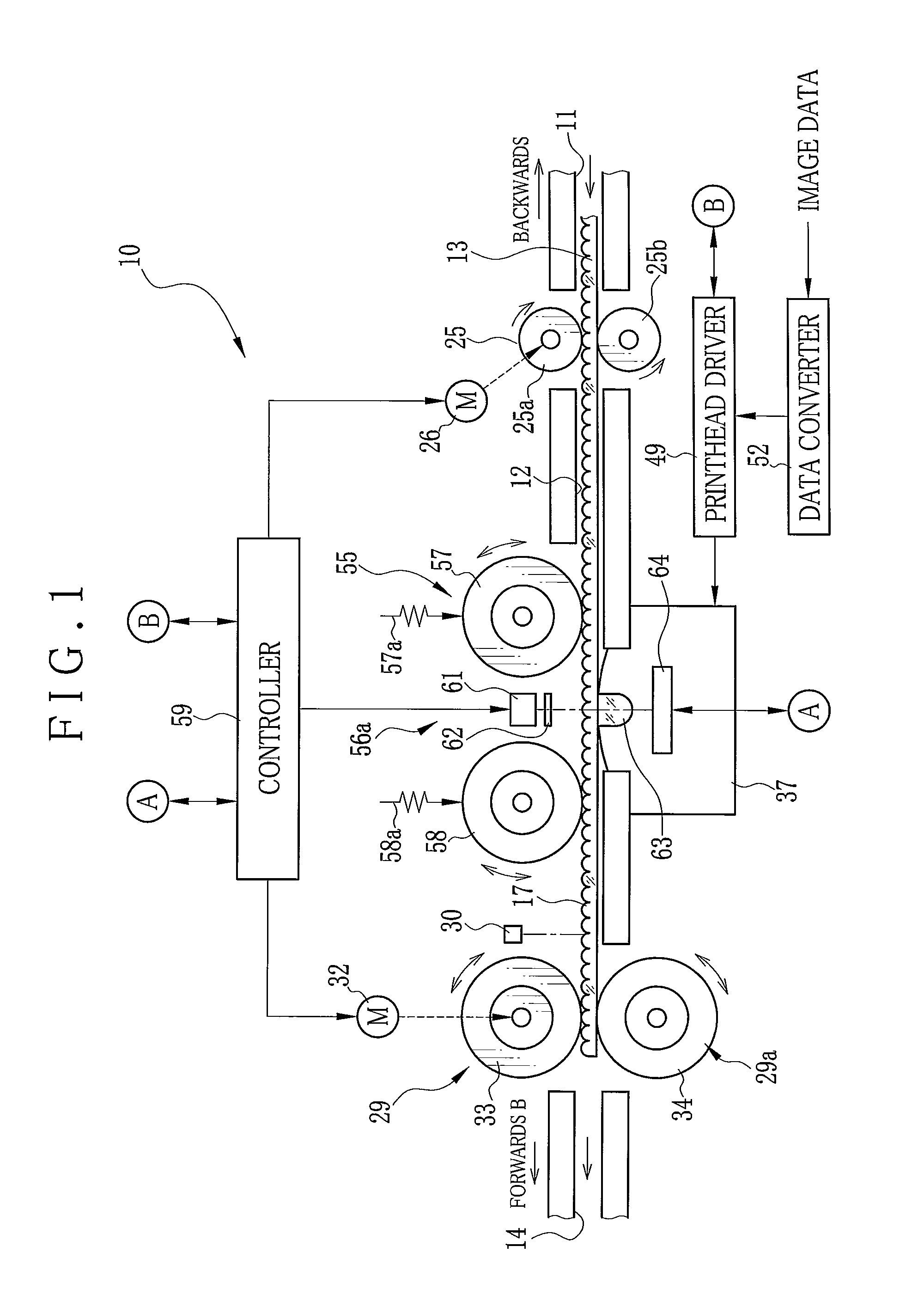
[0099]In the first embodiment, the line sensors 64 and 65 are incorporated in each of the detection units 56a and 56b. In contrast, a second preferred printer 70 is illustrated in FIG. 16, in which one line sensor 73 is incorporated in detection units 72a and 72b which constitute an orientation detector 71. A slit plate 74 has a smaller size than the slit plate 62 in the main scan direction. A cylindrical lens 75 has a smaller size than the cylindrical lens 63 in the main scan direction. This structure makes it possible to reduce a size of the printer 70.
[0100]The printer 70 of the embodiment controls the transport device 29 to match the sensor element positions of the peak values P of the detection signals from the line sensor 73 of the detection units 72a and 72b. In FIG. 11, let F1 and F2 be the detection signals from the line sensor 73 of the detection units 72a and 72b. Let X be a difference between the sensor element positions of the peak values P1 and P2 of the detection sign...
3rd embodiment
[0102]In the first and second embodiments, the orientation is detected and adjusted according to the detection signal of one of the lenticules 17. However, it is possible to detect and adjust the orientation according to detection signals of two of the lenticules 17.
[0103]In FIG. 17, a printer of the embodiment has a detection unit 80 including a slit plate 81 and a cylindrical lens 82. A slit 81a is formed in the slit plate 81 for applying the detection light S to two of the lenticules 17 simultaneously. Two light components S1 and S2 of the detection light are obtained by diffusion in the two of the lenticules 17. The cylindrical lens 82 is disposed with a size D in the sub scan direction suitable for condensing the two light components S1 and S2. As the detection light components S1 and S2 are incident upon the line sensor 64, a detection signal Fw output by the line sensor 64 has two waveforms Fw1 and Fw2 corresponding to the two of the lenticules 17 and two peak values Pw1 and ...
4th embodiment
[0106]In contrast with the above embodiments where the two detection units are used, only one detection unit may be used for the orientation detection and orientation adjustment of the lenticular sheet 13. In FIG. 19, a printer 90 includes one detection unit 91 opposed to one lateral edge portion of the lenticular sheet 13. The detection unit 91 has the projecting light source 61, the slit plate 62, the cylindrical lens 63 and the line sensor 64.
[0107]In FIG. 20, the controller 59 drives the transport roller sets 29a and 29b to nip the lenticular sheet 13. The transport motor 32 is driven to rotate at the smallest pitch (fine pitch) of rotation, to transport the lenticular sheet 13 in the forward direction. After the lenticular sheet 13 is transported, the controller 59 monitors a detection signal of the line sensor 64 to check whether a peak value is at the center of the element array direction or not.
[0108]In FIG. 9, the controller 59 detects a full width at half maximum H (FWHM) ...
PUM
 Abstract
Description
Claims
Application Information
 - R&D
- Intellectual Property
- Life Sciences
- Materials
- Tech Scout
- Unparalleled Data Quality
- Higher Quality Content
- 60% Fewer Hallucinations
Browse by: Latest US Patents, China's latest patents, Technical Efficacy Thesaurus, Application Domain, Technology Topic, Popular Technical Reports.
© 2025 PatSnap. All rights reserved.Legal|Privacy policy|Modern Slavery Act Transparency Statement|Sitemap|About US| Contact US: help@patsnap.com


