
High precision chuck with centering function

a high-precision, chuck technology, applied in the direction of chucks, manufacturing tools, mechanical equipment, etc., can solve the problems insufficient holding-position repeatability and durability, and long time-consuming centering, so as to facilitate coaxial holding of objects, the effect of insufficient centering accuracy and repeatability

Active Publication Date: 2011-05-19
FUJI MASCH MFG CO LTD
View PDF32 Cites 10 Cited by
  • Summary
  • Abstract
  • Description
  • Claims
  • Application Information

AI Technical Summary

Benefits of technology

[0008]The above object may be achieved according to the principle of the present invention, which provides a chuck including: (a) a main body having an central axis (about which the main body is to be rotated); (b) three slot-defining members each constituted by a member independent of the main body and defining therein a guide slot, each of the three slot-defining members having slot-opening-side end surfaces in which the guide slot opens, the three slot-defining members being detachably attached to the main body such that the guide slot of each of the three slot-defining members extends in a radial direction that is perpendicular to the central axis of the main body; (c) three jaws each including (c-1) a fitted portion which is slidably fitted in the guide slot defined in a corresponding one of the three slot-defining members and which has an opening-location surface that is located in the opening of the guide slot of the corresponding one of the three slot-defining members and (c-2) an engaging portion which projects from the fitted portion in an axial direction parallel to the central axis and which is configured to engage with an outer circumferential surface or an inner circumferential surface of an object that is to be chucked by the chuck; (d) three pairs of pressing members detachably fixed to the slot-opening-side and surfaces of the three slot-defining members, each pair of the three pairs of pressing members engaging with the opening-location surface of the fitted portion of a corresponding one of the three jaws, for thereby preventing separation of the fitted portion of the corresponding one of the three jaws from the guide slot defined in a corresponding one of the three slot-defining members; and (e) a jaw driving device configured to cause each of the three jaws to be moved along the guide slot defined in a corresponding one of the three slot-defining members, such that the three jaws are moved in synchronization with one another.
[0088]In the hybrid chuck according to this mode (18), it is possible to further improve the centering accuracy of the three-jaw chuck portion, and accordingly to cause the electromagnetic chuck portion to chuck the object that is centered with a high centering accuracy. In addition to such a high holding-position accuracy, this hybrid chuck provides an advantage that avoids deformation of the object, so as to constitute an ideal chuck. Further, even in a case where the three-jaw chuck portion as well as the electromagnetic chuck portion is placed in the chucking state, it is possible to minimize displacement of the chucked object away from the main body of the chuck by the three jaws. Thus, it can be the that this hybrid chuck constitutes an ideal, chuck that establishes a high holding-position accuracy and a high holding rigidity.

Problems solved by technology

In a conventional three-jaw chuck, however, there have been problems that its centering accuracy, holding-position repeatability and durability are not necessarily satisfactory.
Further, in an electromagnetic chuck, there have been problems that an object to be chucked has to be necessarily made of a magnetic material because of its arrangement for sucking the object by a magnetic suction force, and also that it takes a long time to center and chuck an object because of the arrangement for sucking an end face of the object, namely, because of absence of self-centering function (i.e., function of making an axis of the object aligned with an axis of the chuck).
Particularly, where the chuck has a large size with a diameter of, for example, 1000 mm or more as measured in the main body of the chuck, such a large-sized chuck bee to be machined by limited machining equipments that are capable of performing a large-sized work, thereby problematically requiring a long period of time for manufacturing the chuck.

Method used


Image

  • High precision chuck with centering function
  • High precision chuck with centering function
  • High precision chuck with centering function

Examples


Embodiment Construction

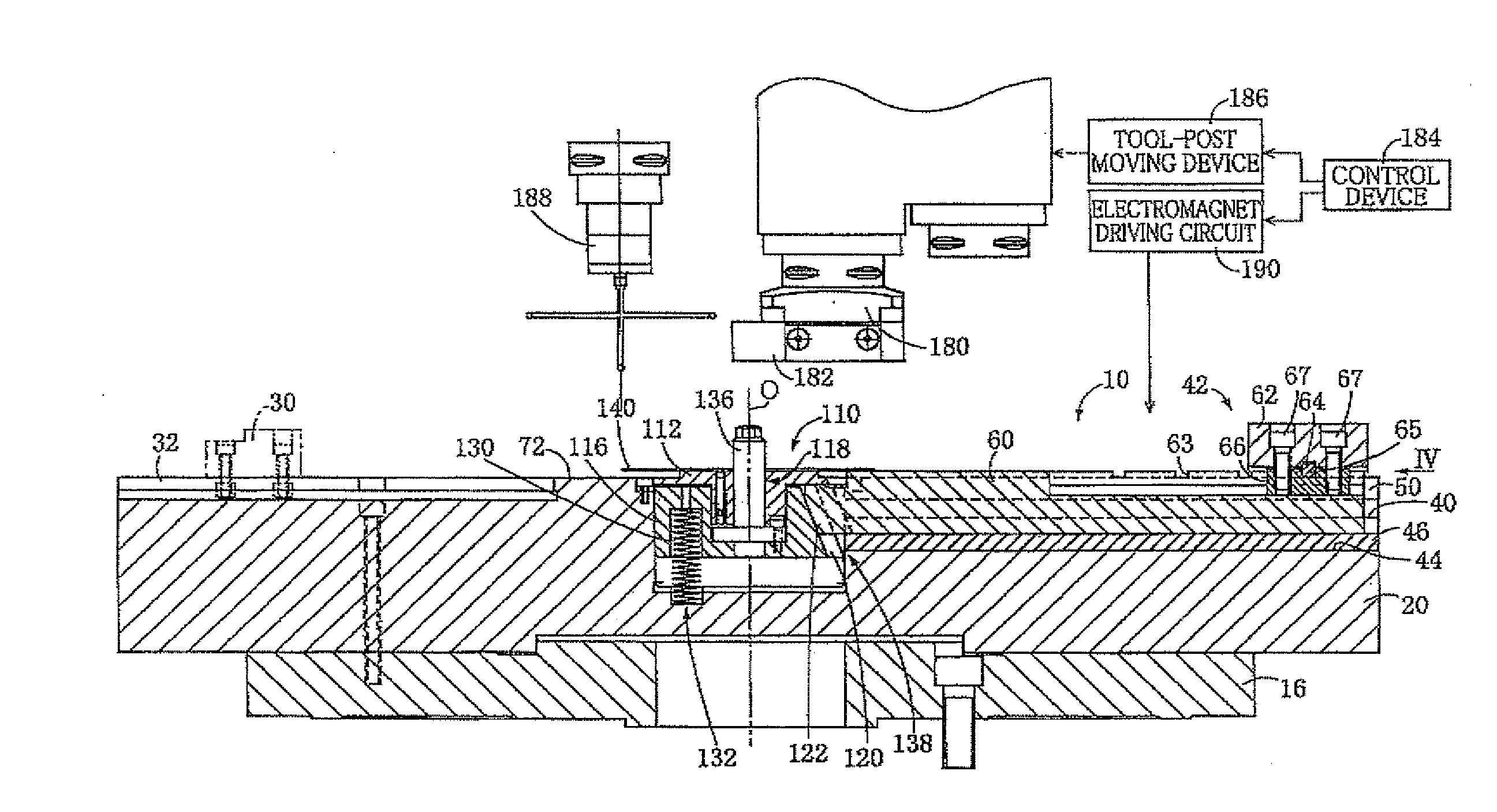
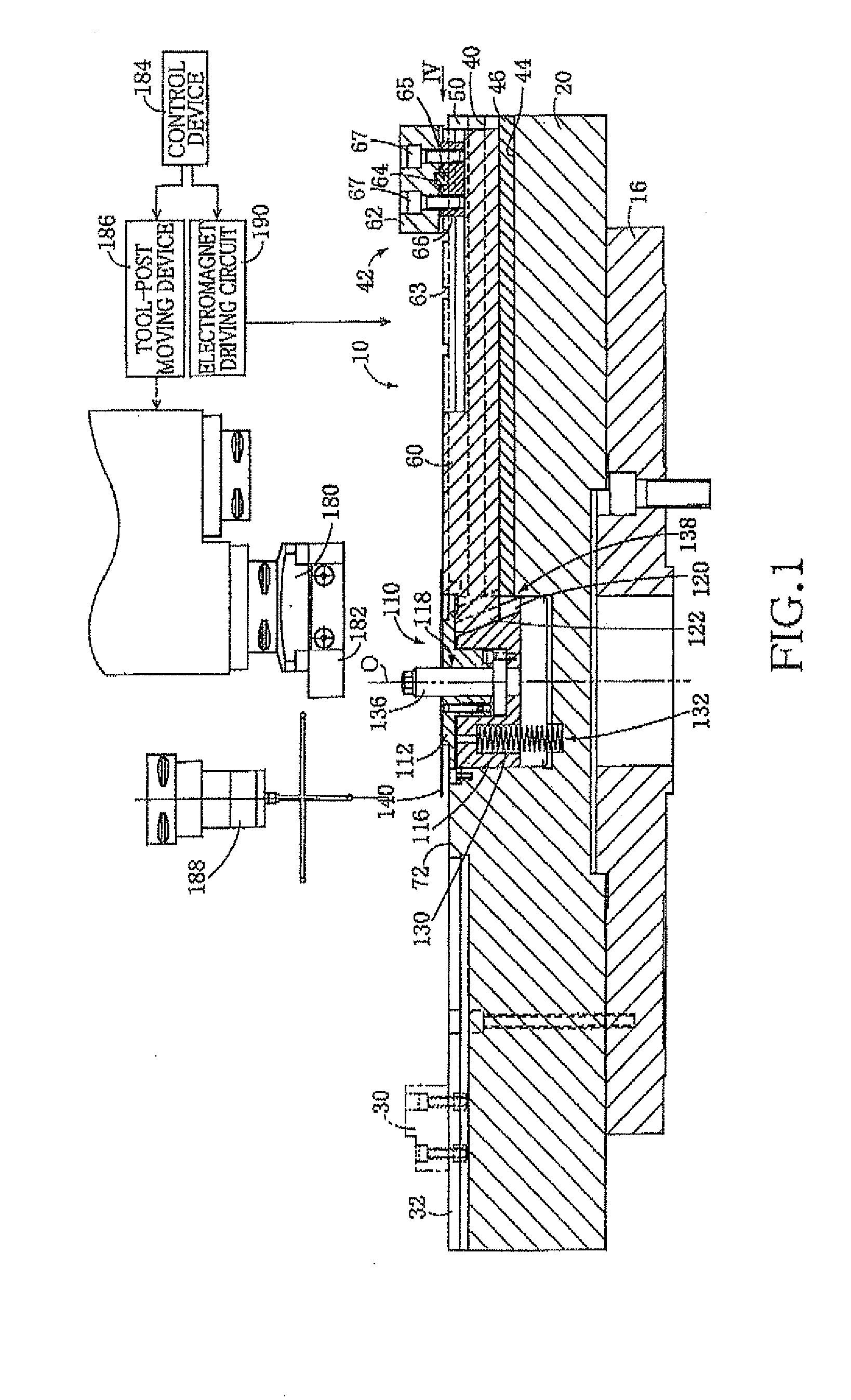
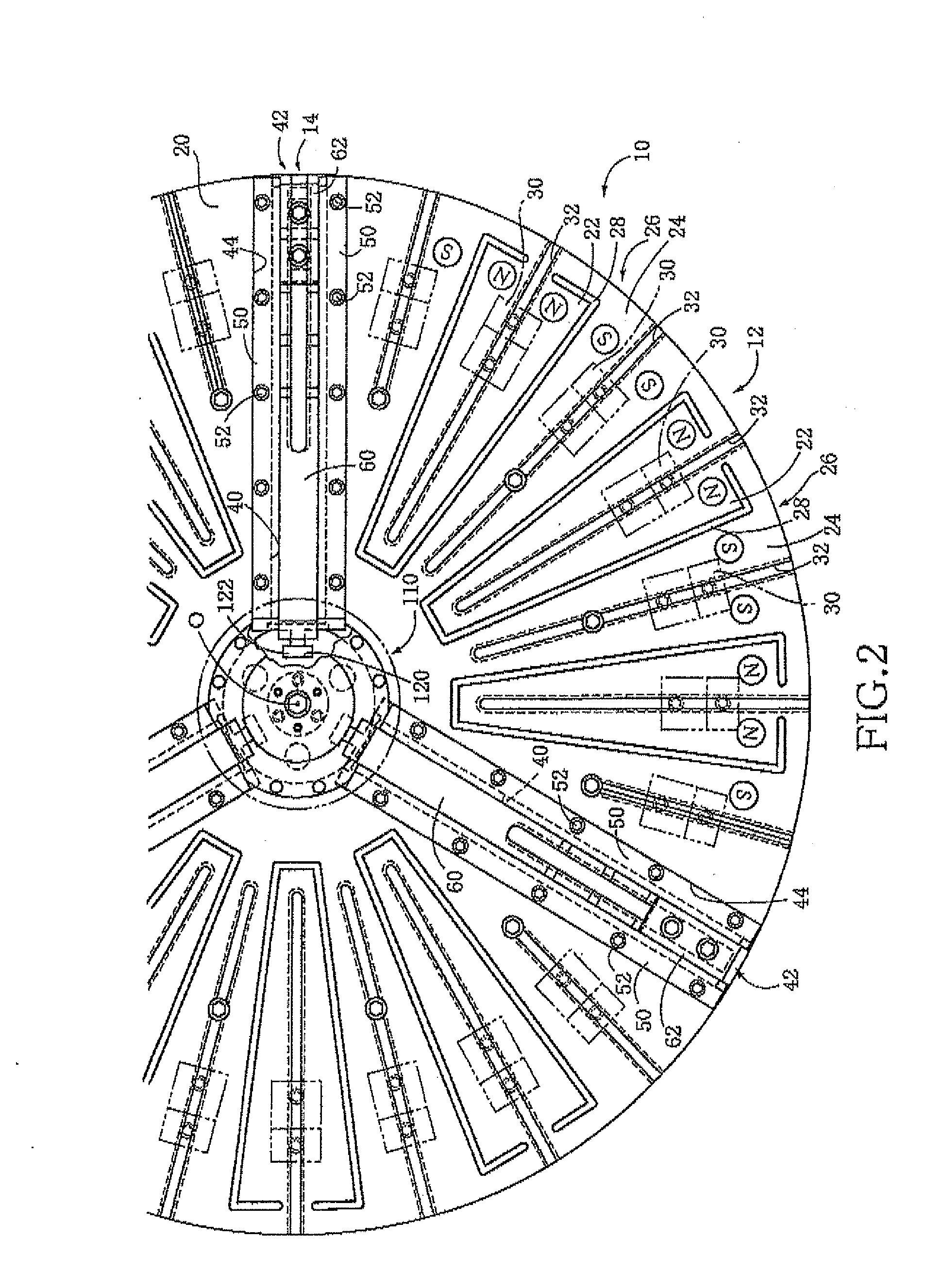
[0100]Referring first to FIGS. 1-4, there will be described a hybrid chuck 10 that is constructed according to an embodiment of the invention. The hybrid chuck 2 has an electromagnetic chuck portion 12 and a three-jaw chuck portion 14 as an universal chuck portion, as shown in FIG. 2, and is to be mounted on a machine tool such as a vertical lathe (i.e., vertical turning center). FIG. 1 shows, by way of example, an arrangement in which the hybrid chuck 10 is attached to a rotary table (i.e., spindle nose) 16 of the vertical lathe, which has a diameter as large as 1000 mm.

[0101]Although the electromagnetic chuck portion 12 which is basically the same as conventional electromagnetic chuck will not be described in detail herein, this electromagnetic chuck portion 12 is formed integrally with a main body 20 of the chuck 10, and has a total of 18 electromagnets 26 each including a N-pole 22 and a S-pole 24. In the main body 20, there are embedded separators 28 made of non-magnetic materi...


PUM

PropertyMeasurementUnit
Forceaaaaaaaaaa
Wear resistanceaaaaaaaaaa

Abstract

A chuck including: (a) a main body; (b) three slot-defining members each constituted by a member independent of the main body and defining therein a guide slot, and detachably attached to the main body; (c) three jaws each including (c-1) a fitted portion slidably fitted in the guide slot defined in the corresponding slot-defining member and (c-2) an engaging portion which projects from the fitted portion in an axial direction and which is configured to engage with a circumferential surface of an object that is to be held by the chuck; and (d) three pairs of pressing members detachably fixed to the three slot-defining members. Each pair of the three pairs of pressing members engage with the fitted portion of the corresponding jaw, for thereby preventing separation of the fitted portion of the corresponding jaw from the guide slot defined in the slot-defining member.

Description

CROSS REFERENCE TO RELATED APPLICATION[0001]This application claims priority from Japanese Patent Application No. 2009-263625 filed on Nov. 19, 2009, the disclosure of which is herein incorporated by reference in its entirety.BACKGROUND OF THE INVENTION[0002]1. Field of the Invention[0003]The present invention relates to improvement in a chuck configured to chuck an object and having a self-centering function.[0004]2. Discussion of Related Art[0005]There is widely used a three-jaw chuck as an universal chuck for coaxially chucking an object such as a workplace that is to be machined. The three-jaw chuck generally includes: a main body; three jaws held on the main body and movable relative to the main body in respective radial directions; and a jaw driving device configured to move the three jaws in synchronization with one another so that the object can be held at its outer circumferential surface or inner circumferential surface by cooperation of the three jaws. On the other hand, ...

Claims


Application Information

Patent Timeline
IPC IPC(8): B23B31/16
CPCB23B31/16233B23B31/16266Y10T279/1986B23B2270/38B23Q3/152B23B31/28B23B3/06Y10T82/2511Y10T279/10Y10T279/19Y10T279/1993Y10T279/21Y10T279/23Y10T279/29
Inventor OGAWA, GENISOZUMI, JOJINAGAI, OSAMU
Owner FUJI MASCH MFG CO LTD
Learn More