Energy storage caddy for a welding system

a technology of energy storage and caddy, which is applied in the field of welding systems, can solve the problems of reducing portability, reducing the portability of the overall package, and presenting a high monetary cost of replacing a traditional welder with a hybrid system

Active Publication Date: 2011-05-19
ILLINOIS TOOL WORKS INC
View PDF58 Cites 26 Cited by
  • Summary
  • Abstract
  • Description
  • Claims
  • Application Information

AI Technical Summary

Benefits of technology

[0005]In another embodiment, a retrofit kit for a welding system includes an energy storage caddy adapted to generate a power output and to provide the generated power output to a welding power supply. The energy storage caddy includes an energy storage device adapted to discharge to produce the power output and control circuitry coupled to the energy storage device and adapted to regulate the power output based on a charge level of the energy storage device, a load demand at the welding power supply, and a temperature of the energy storage device.

Problems solved by technology

Unfortunately, to replace a traditional welder with a hybrid system may present a high monetary cost.
Furthermore, the incorporation of alternate power sources into the welder may add to the bulkiness of the overall package, thus decreasing portability.

Method used


Image

  • Energy storage caddy for a welding system
  • Energy storage caddy for a welding system
  • Energy storage caddy for a welding system

Examples


Embodiment Construction

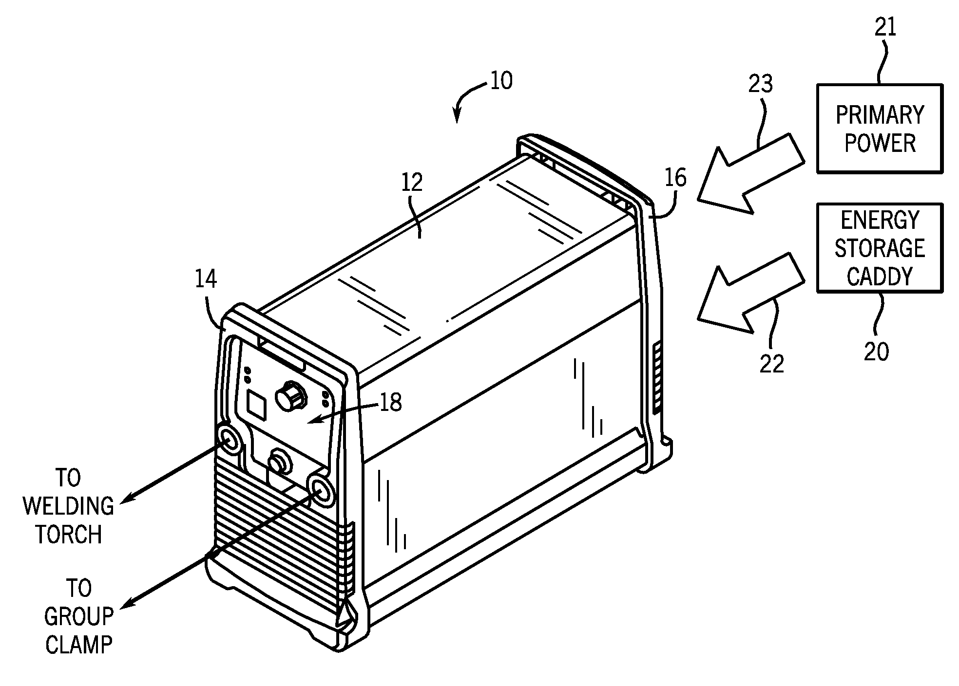
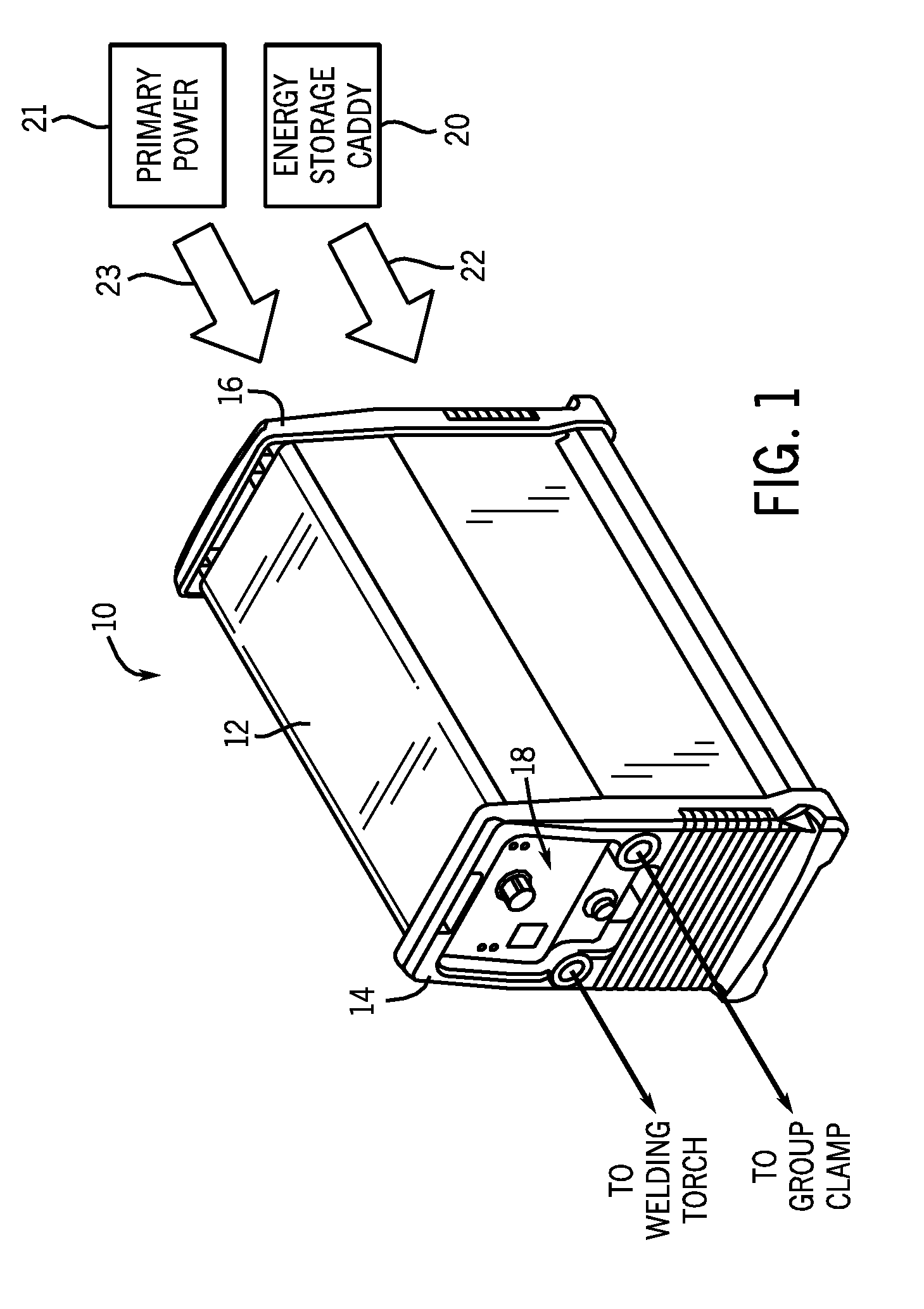
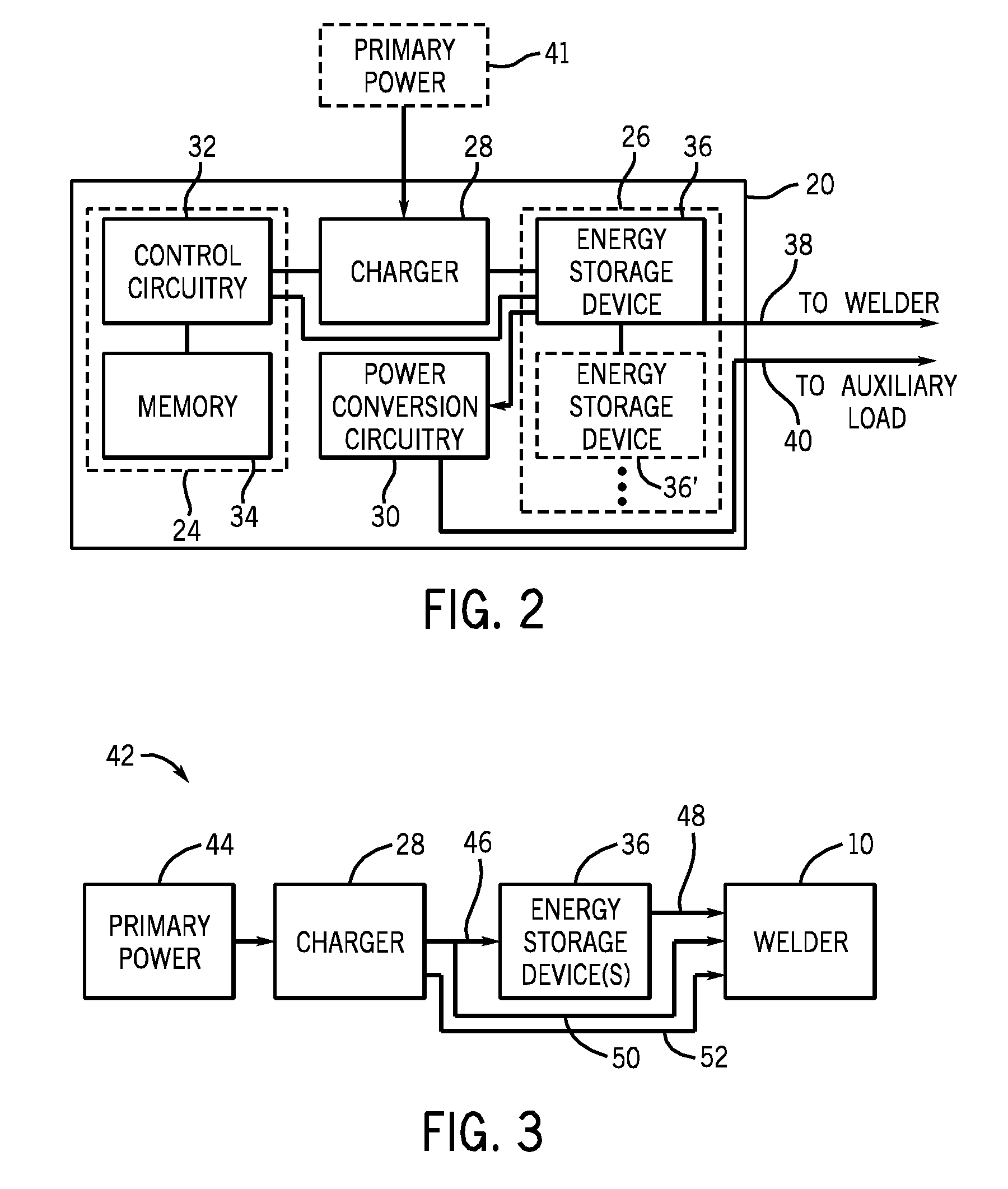
[0012]As described in detail below, embodiments of an energy storage caddy adapted to retrofit existing welding power supplies is provided. The energy storage caddy is adapted to provide primary power to a welding power supply, which may include power conversion circuitry configured to convert the received power to an appropriate weld power output. To that end, the energy storage caddy may include one or more energy storage devices, such as batteries, fuel cells, and so forth, capable of providing power (e.g., by discharging) without the need for any external connections. That is, the energy storage caddy is capable of operating as a standalone unit during operational periods. Furthermore, the energy storage caddy may be capable of recharging the one or more energy storage devices disposed therein, for example, via coupling to an external or internal charger and primary power supply.

[0013]Turning now to the drawings, FIG. 1 is a perspective view of an exemplary welding system 10 in ...


PUM

PropertyMeasurementUnit
DC voltageaaaaaaaaaa
poweraaaaaaaaaa

Abstract

Embodiments of energy storage caddies adapted to couple to a welding power supply are provided. The energy storage caddies may include an energy storage device, a charger, control circuitry, and power conversion circuitry. Certain control circuitry may be adapted to control the energy storage device to discharge to provide a direct current (DC) voltage output to the welding power supply when a weld load demand is detected, to monitor a charge level of the energy storage device, and to alert a user to an error when the charge level of the energy storage device falls below a predetermined limit.

Description

CROSS REFERENCE TO RELATED APPLICATIONS[0001]This application is a Non-Provisional Patent Application of U.S. Provisional Patent Application No. 61 / 261,958 entitled “Battery Pack”, filed Nov. 17, 2009, which is herein incorporated by reference.BACKGROUND[0002]The invention relates generally to welding systems and, more particularly, to primary power supplies for welding power sources.[0003]Welding is a process that has become increasingly ubiquitous in various industries and applications. As such, a variety of welding applications, such as in construction and shipbuilding, may require welding devices that are portable and can easily be transported to a remote welding location. Accordingly, it is often desirable for such welding devices to be operable as standalone units remote from a power grid or other stationary primary power source. Unfortunately, to replace a traditional welder with a hybrid system may present a high monetary cost. Furthermore, the incorporation of alternate pow...

Claims


Application Information

Patent Timeline
Patent Type & Authority Applications(United States)
IPC IPC(8): B23K11/26
CPCB23K9/1006B23K9/1056H01M10/0525H01M10/30H02J7/0063H01M10/46H01M10/48H02J7/0047H01M10/345Y02E60/10H02J7/007
Inventor ALBRECHT, BRUCE PATRICK
Owner ILLINOIS TOOL WORKS INC
Why Eureka
Try Eureka