Systems and Methods for the Separation of Propylene and Propane
a technology of propylene and propane, applied in the separation process, membranes, filtration separation, etc., can solve the problems of increasing non-ideality of the stream, temperature change, temperature decrease on separation, etc., and achieve the effect of simplifying the design and operation of the system
- Summary
- Abstract
- Description
- Claims
- Application Information
AI Technical Summary
Benefits of technology
Problems solved by technology
Method used
Image
Examples
example 1
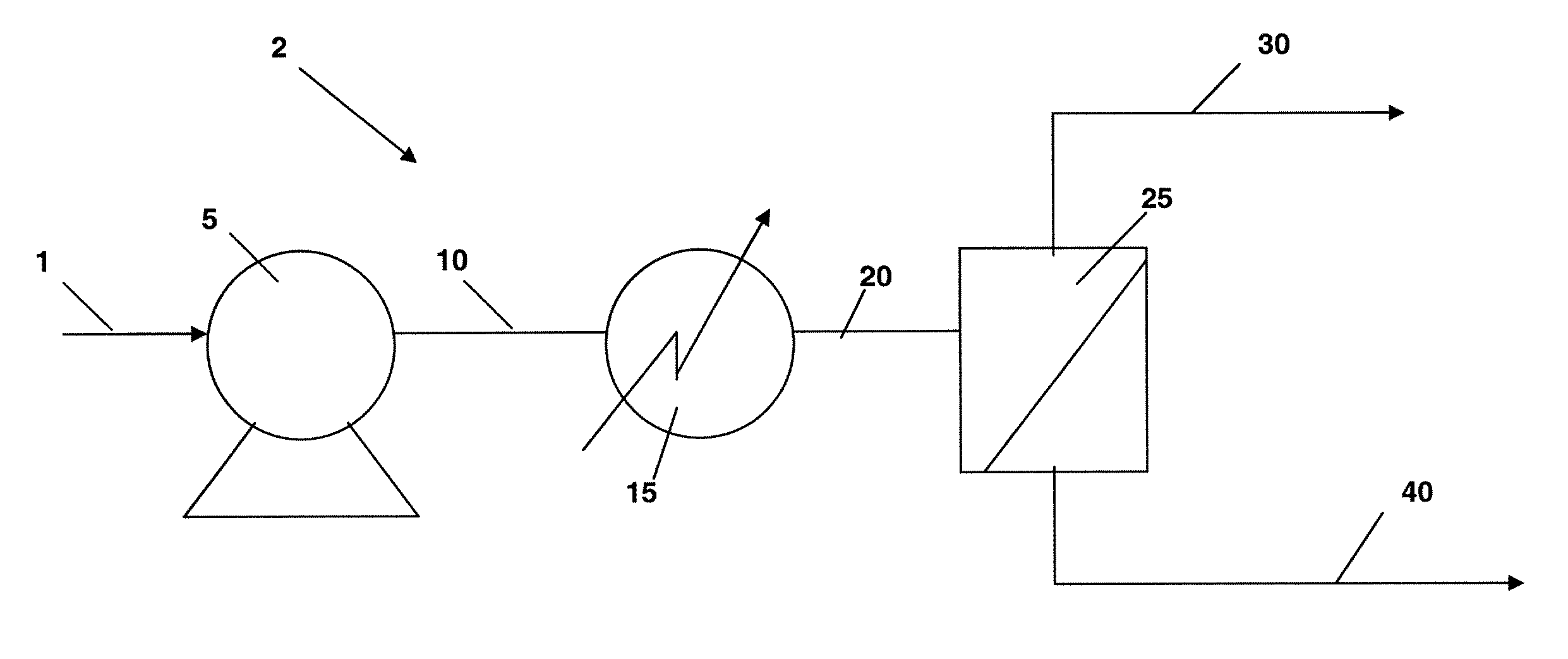
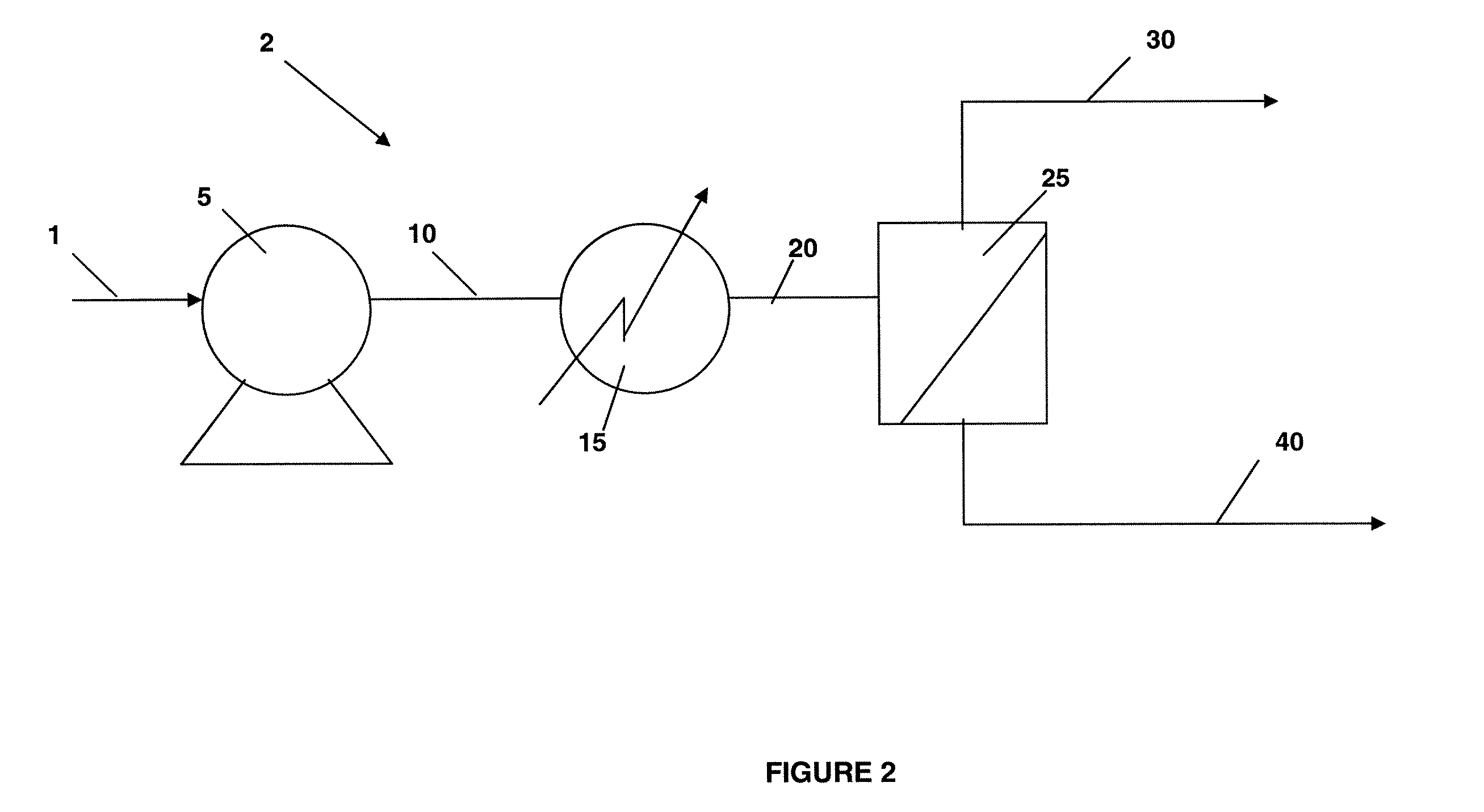
[0084]A simulation was performed based upon the system illustrated in FIG. 2. The intent of this system is the recovery of higher purity propylene. The system incorporates a membrane (25) with a propylene to propane selectivity of 11.3 MMscfd. Now referring to FIG. 2, an example of a system of the present invention for the separation of propylene and propane is disclosed. A feed of 3 MMscfd at 200 psia and 30C is introduced to System 2. Pump 5 pressurizes the stream 500 psia. Evaporator (15) vaporizes the feed reaching an ultimate temperature of 90° C. Membrane (25) with an inherent propylene to propane selectivity of 11 is used to separate the feed into a propylene enriched product (40) and a propane enriched product (30). The propylene product is recovered at 93% propylene purity at 40 psia. Propylene recovery is 70%. The propane purity is 57% and propane recovery is 88%. The pump for this system requires 44 kw and the evaporator (heat exchanger) requires 662 kW. Table 1 lists the...
example 2
[0085]A simulation was also performed based upon the system illustrated in FIG. 3. The system is capable of high recovery of increased purity propylene and high recovery of increased purity propane. A feed of 3 MMscfd at 200 psia and 30C is introduced to the system outline in FIG. 2. Pump (315) pressurizes the stream 500 psia. Evaporator (heat exchanger) (325) vaporizes the feed reaching an ultimate temperature of 90° C. Membrane (335) separates the feed into a propylene enriched product at 40 psia (390). The propylene product is compressed to system feed pressure by Compressor (395). The non-permeate stream (340) is reheated to 9° C. and further processed by membrane (335) into a 95% propane product (50) and a low pressure propylene-enriched stream. Stream 360 is compressed by compressor (364) and subsequently condensed by condenser (375). The resulting stream is comingled with the feed (301). The combined stream is fed to the membrane system.
A system based on FIG. 3 is capable of ...
example 3
demonstrates identical performance to Example 2 without the necessity of propylene product compression.
TABLE 4Stream Properties for Example 3Stream #401420430490440441450460T (° C.)3032908282903535P (psia)2005005004049949949930V / L00110.810.51Flow (MMscfd)35.495.492.23.273.270.782.49% propylene7076.2976.2993.163.763.74.982.1% propane3023.7123.716.936.336.395.117.8
PUM
| Property | Measurement | Unit |
|---|---|---|
| feed pressure | aaaaa | aaaaa |
| temperatures | aaaaa | aaaaa |
| pressure | aaaaa | aaaaa |
Abstract
Description
Claims
Application Information
 - R&D
- Intellectual Property
- Life Sciences
- Materials
- Tech Scout
- Unparalleled Data Quality
- Higher Quality Content
- 60% Fewer Hallucinations
Browse by: Latest US Patents, China's latest patents, Technical Efficacy Thesaurus, Application Domain, Technology Topic, Popular Technical Reports.
© 2025 PatSnap. All rights reserved.Legal|Privacy policy|Modern Slavery Act Transparency Statement|Sitemap|About US| Contact US: help@patsnap.com


