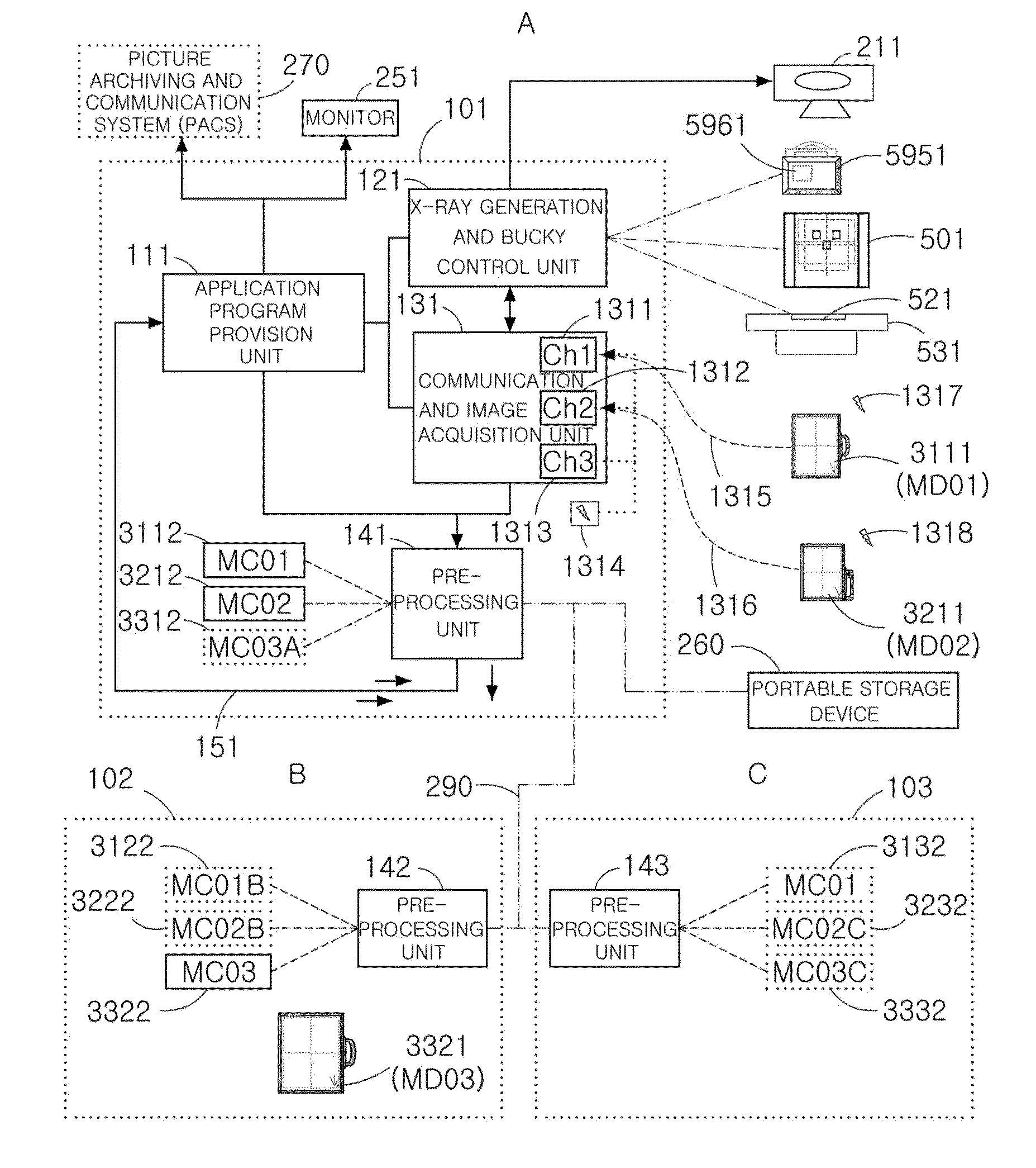
Digital radiography system
Active Publication Date: 2011-05-12
LEE JONG IN
View PDF11 Cites 39 Cited by
- Summary
- Abstract
- Description
- Claims
- Application Information
AI Technical Summary
Benefits of technology
[0053]A digital radiography system in accordance with the present invention uses electronic cassettes in replace of fixed flat panel detectors, and thus is capable of employing various radiography techniques, minimizes an amount of radiation exposed to a patient, prevents unnecessary enlargement of an image, and allows a radiography position minimizing movement of an emergent patient or a serious patent to be freely selected.
[0054]Further, the digital radiography system allows the electronic cassettes to be interchangeably mounted on and detached from other digital radiography systems in real time by an operator, thereby maximizing efficiency in use of the expensive electronic cassettes at the minimum number of the electronic cassettes.
[0055]Further, each of the electronic cassettes includes channel display units, thereby minimizing operator's confusion due to use of the same electronic cassette.
[0056]Further, each of the electronic cassettes includes an electronic cassette selection switch, thereby allowing one electronic cassette to be selected from among the plural electronic cassettes used in the digital radiography system.
[0057]Further, since a large area electronic cassette, a small area electronic cassette, an image plate cassette, and a film cassette may be freely selectively mounted on a bucky tray, and thus efficiency in use of the digital radiography system is increased.
[0058]Further, an ID chip of the electronic cassette mounted on the bucky tray is read and a mount state of the electronic cassette is recognized in real time so as to maximize automation in radiography, and if the mount state of the electronic cassette is not normal, generation of X-rays is prevented and thus unnecessary amount of radiation exposed to a patient is reduced.
Problems solved by technology
In the above analog detection method, consumable costs of the film are continuously generated during a development process, the film is used to perform all processes, such as image acquisition, display, storage, and transmission media, and thus requires close attention and causes a difficulty in maintenance of the film, increase of maintenance costs, and a lot of risk of loss and damage, a development waste liquid causes environmental pollution and thus obstructs hospital environments, and time consumption due to the development process delays a consultation time of a patient and thus improvement in medical service environments is urgently required.
Conventional flat panel detectors used for the clinical purpose mostly satisfy the above requirements, but are not satisfactory in size and weight and are used only in a state in which the flat panel detectors are fixed to the inside of a table bucky or a stand bucky, thus causing several problems, as follows.
First, special radiography techniques for diagnosis are limited.
However, since movement of the fixed flat panel detector is restricted, radiography in the horizontal direction or radiography in the axial direction is not performed or radiography is performed only in an inconvenient pose of a patient, and thus acquisition of a diagnostically valuable image is limited.
Particularly, if a serious patient or an emergent patient needs to be radiographed as being located on a portable patient bed, the digital radiography system using the fixed flat panel detectors cannot perform radiography of such a patient.
However, the image plate is deteriorated according to the number of times of radiography, and needs to be replaced with a new one through image deterioration measurement.
If both radiography using the flat panel detector and radiography using the image plate are performed with respect to one patient, diagnosis through comparison between two digital images is very difficult.
Since the two detectors are different in aspects of characteristics and image processing techniques thereof, it is difficult for an image reading doctor to diagnose the patient through comparison between the two digital images.
If the grid is fixed to the bucky, the grid must be used even in radiography not requiring the grid, and thus radiography conditions are raised as much as a sufficient amount of primary rays due to use of the grid, thereby causing increase in an amount of radiation exposed to a patient and raise in load of an X-ray tube.
Fourth, if the detector is replaced, it takes a long time to complete the replacement until service complement.
Therefore, the expensive digital radiography system cannot be used for a long period of time.
Therefore, the image plate cassette and the film cassette repeat mount within the bucky and detachment from the bucky whenever radiography is performed, thereby providing user's inconvenience.
Method used
View moreImage
Smart ImageViewing Examples
Examples
Embodiment Construction
[0156]Various embodiments have been described in the best mode for carrying out the invention.
[0157]Although the preferred embodiments of the present invention have been disclosed for illustrative purposes, those skilled in the art will appreciate that various modifications, additions and substitutions are possible, without departing from the scope and spirit of the invention as disclosed in the accompanying claims.
Login to View More PUM
 Abstract
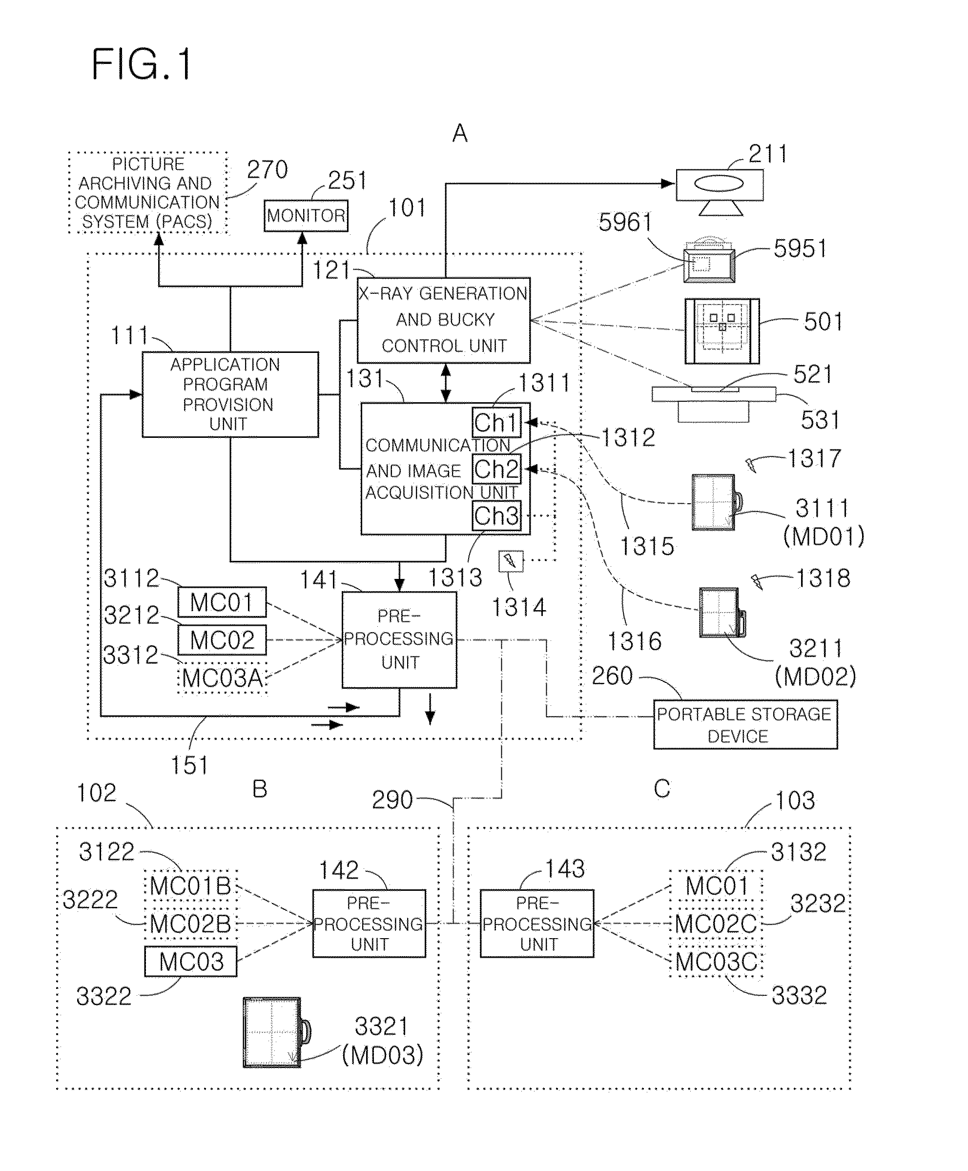
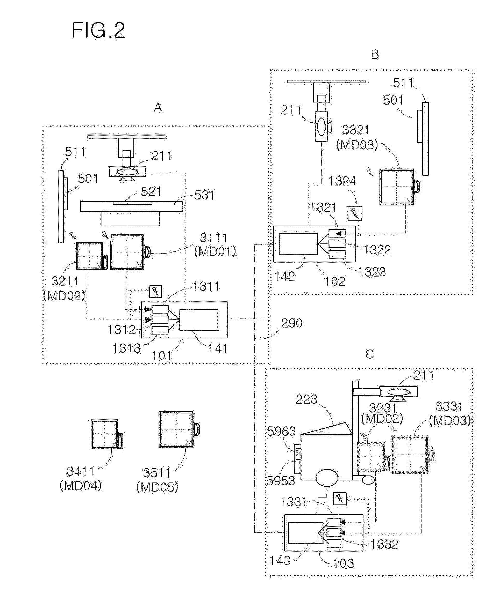
Disclosed herein is a digital radiography system which provides detachable and portable flat panel detectors (hereinafter, referred to as ‘electronic cassettes’) and transreceives data recorded in the electronic cassettes in on-line through a network. The digital radiography system includes bucky trays on which a plurality of portable electronic cassettes is detachably mounted, and a workstation connected with the bucky trays through communication to identify the plurality of portable electronic cassettes mounted on the bucky trays and to download pre-processing files of the identified electronic cassettes through the network or a portable storage device or to store files, generated by the plurality of electronic cassettes, in the storage device.
Description
TECHNICAL FIELD[0001]The present invention relates to a digital radiography system used in a medical imaging system, and more particularly to a digital radiography system which provides detachable and portable flat panel detectors (hereinafter, referred to as ‘electronic cassettes’) and transreceives data recorded in the electronic cassettes in on-line through a network or off-line.BACKGROUND ART[0002]In general, radiography systems for medical diagnosis irradiate X-rays onto a human body and detect an energy intensity distribution difference between the X-rays transmitted by the human body. Detection methods of these radiography systems are divided into an analog type and a digital type.[0003]In the analog detection method, an intensifying screen (a fluorescent plate) which emits light when it receives X-rays and a silver salt film are combined, a latent image is formed on the silver salt film using the light generated by the intensifying screen, and then chemical treatment is carr...
Claims
Login to View More Application Information
Patent Timeline
 IPC IPC(8): A61B6/00H05G1/64
CPCA61B6/4494G03B42/04A61B6/00A61B6/06
Inventor LEE, JONG IN
Owner LEE JONG IN
Features
- Generate Ideas
- Intellectual Property
- Life Sciences
- Materials
- Tech Scout
- Unparalleled Data Quality
- Higher Quality Content
- 60% Fewer Hallucinations
Learn More Browse by: Latest US Patents, China's latest patents, Technical Efficacy Thesaurus, Application Domain, Technology Topic, Popular Technical Reports.
© 2025 PatSnap. All rights reserved.Legal|Privacy policy|Modern Slavery Act Transparency Statement|Sitemap|About US| Contact US: help@patsnap.com


