
System and method for adaptive nonlinear compressed visual sensing

Inactive Publication Date: 2011-05-12
GENERAL ELECTRIC CO
View PDF2 Cites 30 Cited by
  • Summary
  • Abstract
  • Description
  • Claims
  • Application Information

AI Technical Summary

Benefits of technology

[0005]There is thus provided a method of compressed sensing of an image, the method comprising first calculating an approximation of a portion of the image, performing at least one nonlinear measurement of the image portion, second calculating an error on the image portion in accordance with the image approximation and the at least one nonlinear measurement, if the error is greater than a threshold, sub-dividing the image portion into a plurality of image portions and recursively repeating first calculating, performing at least one nonlinear measurement, second calculating and dividing until the error is less than or equal to the threshold for all image portions.
[0006]There is also provided a method of compressed sensing of an image, the method comprising performing one or more linear measurements on portions of the image, performing one

Problems solved by technology

As the size of the imaging areas and the accompanying number of pixels of CCDs and other imaging devices grows, however, these devices produce larger and larger datasets.

Method used


Image

  • System and method for adaptive nonlinear compressed visual sensing
  • System and method for adaptive nonlinear compressed visual sensing
  • System and method for adaptive nonlinear compressed visual sensing

Examples


first embodiment

Linear Compressed Visual Sensing

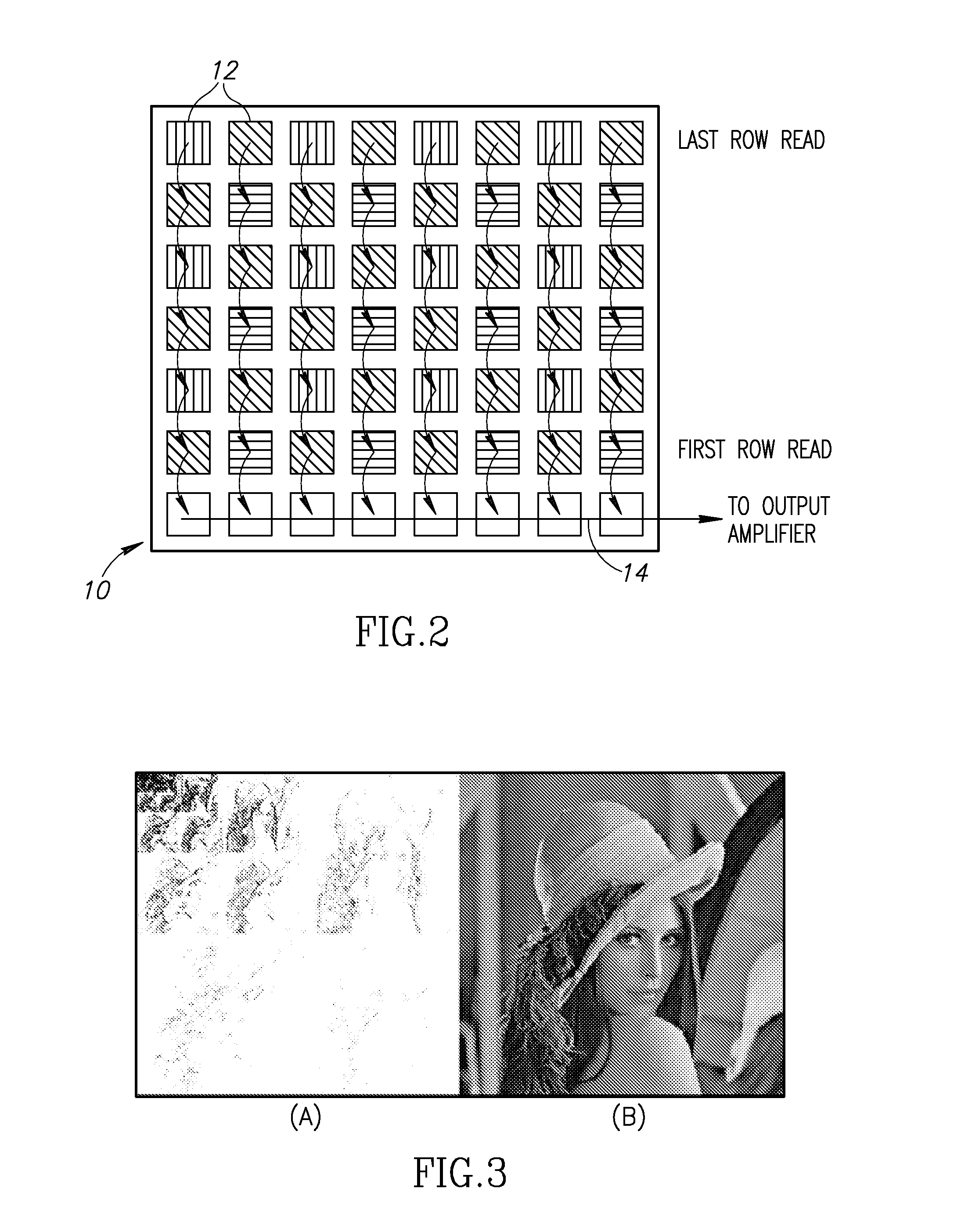
[0035]Consider a digital camera as an example imaging device incorporating a CCD imaging chip. An example CCD imaging sensor as found in a typical digital camera is shown in FIG. 2. The CCD, generally referenced 10, comprises a photoactive region containing a grid of pixels 12. Assume x is a digital image consisting of N pixels that are to be acquired. Some digital cameras perform the image acquisition using an array of N CCDs. The electrical charge generated on each pixel by exposure of the CCD to light is coupled or transferred using appropriate clocking signals from row to row until read out (i.e. shifted out) and fed to an output amplifier at the last row (14). They then undergo a conversion from analog to digital. Another technology known as Complementary Metal Oxide Semiconductor (CMOS) allows high end digital cameras to acquire approximately 12 million pixels (3000×4000).

[0036]Once the digital image x has been acquired, it is usually then compr...

second embodiment

Adaptive Nonlinear Compressed Visual Sensing

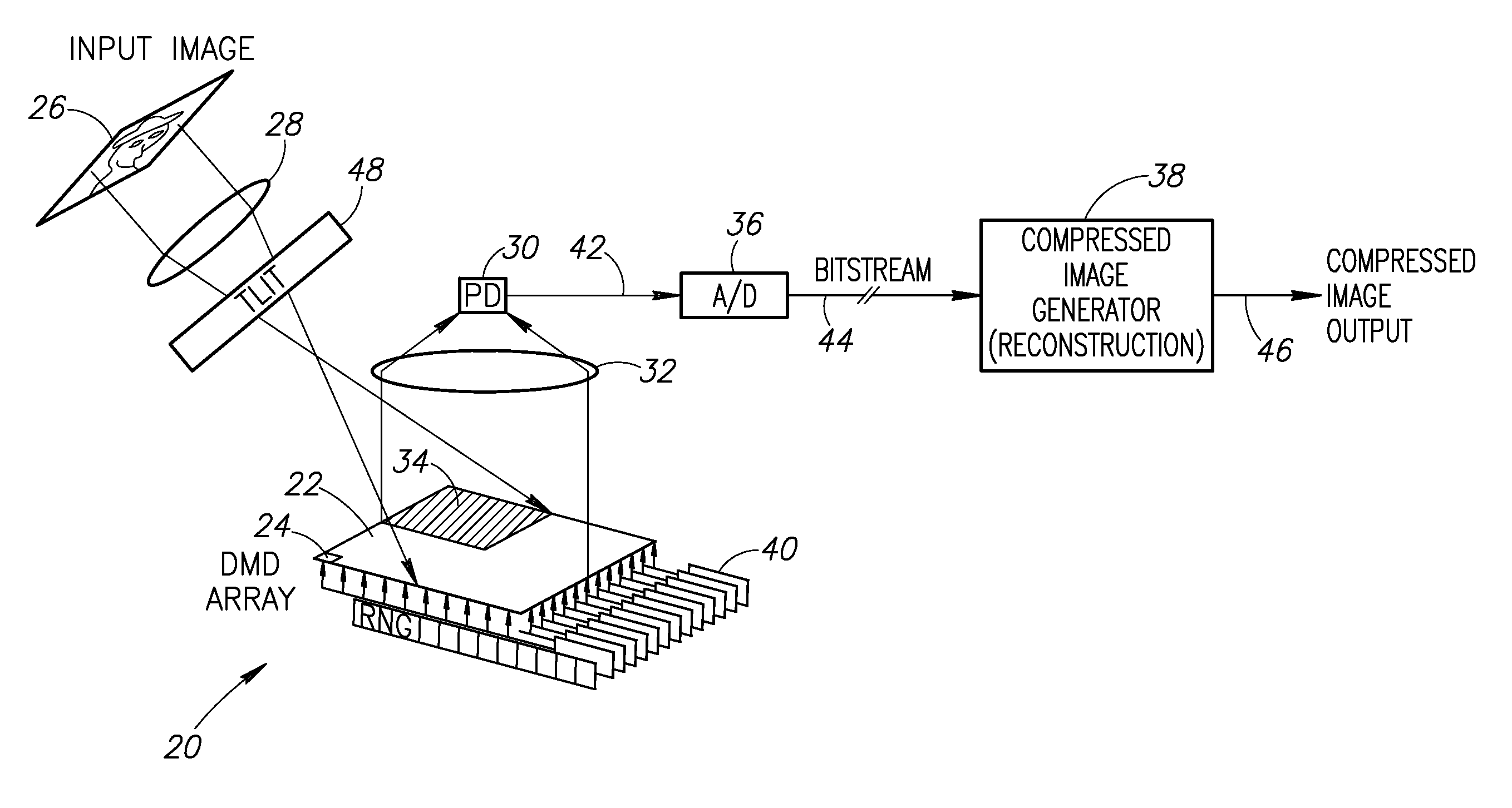
[0056]In this second embodiment, an adaptive nonlinear compressed visual sensing mechanism is described. The adaptive nonlinear compressed sensing mechanism provides a DMD sensing architecture modified to include a nonlinear optical intensifier placed before the DMD array to generate nonlinear samples.

[0057]The DMD architecture enables several embodiments of nonlinear sampling to generate the compressed image. A complimentary decoding process is used to reconstruct the compressed image is no more computational intensive than existing algorithms in use today such as JPEG or JPEG2000 decoding.

[0058]The adaptive nonlinear compressed sensing mechanism is a direct and adaptive approach to compressed sensing. The DMD array architecture is used differently than in the first embodiment as described infra. The particular DMD used, however, is not critical to the invention as one skilled in the art can adapt a particular DMD array to a particular im...


PUM


Abstract

A novel and useful system and method for adaptive nonlinear compressed visual sensing. The adaptive nonlinear compressed sensing mechanism provides a modified DMD sensing architecture incorporating a nonlinear optical intensifier coupled with a nonlinear acquisition process. The modified DMD sensing architecture and related circuitry and software are operative to perform nonlinear image acquisition by computing both linear and nonlinear functionals. These computations are performed recursively to approximate the image to achieve any desired target image quality.

Description

FIELD OF THE DISCLOSURE[0001]The subject matter disclosed herein relates to the field of digital imaging, and more particularly relates to a method and system for adaptive nonlinear compressed visual sensing.BACKGROUND[0002]Currently, the use of acquisition devices such as charge coupled devices (CCDs) is widespread. A CCD is a device for the movement of electrical charge, usually from within the device to an area where the charge can be manipulated, for example conversion into a digital value. This is achieved by shifting the signals between stages within the device one at a time. CCDs are actually implemented as shift registers that move charge between capacitive bins in the device, with the shift allowing for the transfer of charge between bins.[0003]The CCD is usually integrated with a sensor, such as a photoelectric device to produce the charge that is being read, thus making the CCD a major technology where the conversion of images into a digital signal is required. CCDs are c...

Claims


Application Information

Patent Timeline
IPC IPC(8): H04N5/217H04N5/228H04N5/225
CPCH04N5/335H04N25/00
Inventor DEKEL, SHAI
Owner GENERAL ELECTRIC CO
Learn More