
Liquid droplet ejecting head, method for manufacturing the same, and liquid droplet ejecting apparatus

a technology of liquid droplet ejection and ejecting head, which is applied in the direction of electrical transducers, printing, and piezoelectric/electrostrictive/magnetostrictive devices, etc. it can solve the problems of reduced yield in the manufacturing process, inability to easily cover adhesives with a certain thickness or less, and fluidity, so as to achieve high reliability

Active Publication Date: 2011-05-12
SEIKO EPSON CORP
View PDF2 Cites 13 Cited by
  • Summary
  • Abstract
  • Description
  • Claims
  • Application Information

AI Technical Summary

Benefits of technology

[0009]An advantage of some aspects of the invention is to provide a liquid droplet ejecting head with high reliability.
[0010]An advantage of some aspects of the invention is to provide a liquid droplet ejecting head manufactured by a simple process with high productivity.
[0011]An advantage of some aspects of the invention is to provide a simple manufacturing method with high productivity of a liquid droplet ejecting head.
[0015]According to one aspect of the invention, it may be possible to provide a liquid droplet ejecting head in which no adhesive exists between the support substrate and the diaphragm serving as the substrate on which a piezoelectric element is formed. Thus, since no adhesive is used at the time of a process of gluing the support substrate to the diaphragm, an adhesive having fluidity is prevented from being introduced into an ink path, an area where the piezoelectric element is formed, and the like. Consequently, it may be possible to provide a liquid droplet ejecting head with high reliability.
[0016]Furthermore, according to the invention, an etching process of the support substrate may be simplified and an adhesive transfer process of gluing the support substrate to the diaphragm may be omitted. Consequently, it may be possible to provide a liquid droplet ejecting head manufactured by a simple process with high productivity.
[0022]According to the invention, an etching process of the support substrate may be simplified and an adhesive transfer process of gluing the support substrate to the diaphragm may be omitted. Consequently, it may be possible to provide a liquid droplet ejecting head manufactured by a simple process with high productivity.

Problems solved by technology

In the case of using the adhesive in order to glue the support substrate to the substrate having the piezoelectric element, since the adhesive has viscosity, the adhesive may not easily be coated with a certain thickness or less and has fluidity.
Therefore, it is probable that the adhesive may flow into an ink supply path formed in a fluid path forming plate at the time of the gluing process and the ink path may not be sufficiently ensured.
Further, in the case of using the adhesive having fluidity, it is probable that liquid dripping and the like may occur in the transfer process of the adhesive, thereby causing the reduction in the yield in the manufacturing process.

Method used


Image

  • Liquid droplet ejecting head, method for manufacturing the same, and liquid droplet ejecting apparatus
  • Liquid droplet ejecting head, method for manufacturing the same, and liquid droplet ejecting apparatus
  • Liquid droplet ejecting head, method for manufacturing the same, and liquid droplet ejecting apparatus

Examples


Embodiment Construction

[0042]Hereinafter, one embodiment of the present invention will be described with reference to the accompanying drawings. However, the invention is not limited to the following embodiment. The invention includes arbitrary combinations of the following embodiment and modified examples thereof.

1. Liquid Droplet Ejecting Head

[0043]Hereinafter, the liquid droplet ejecting head in accordance with the present embodiment will be described with reference to the accompanying drawings.

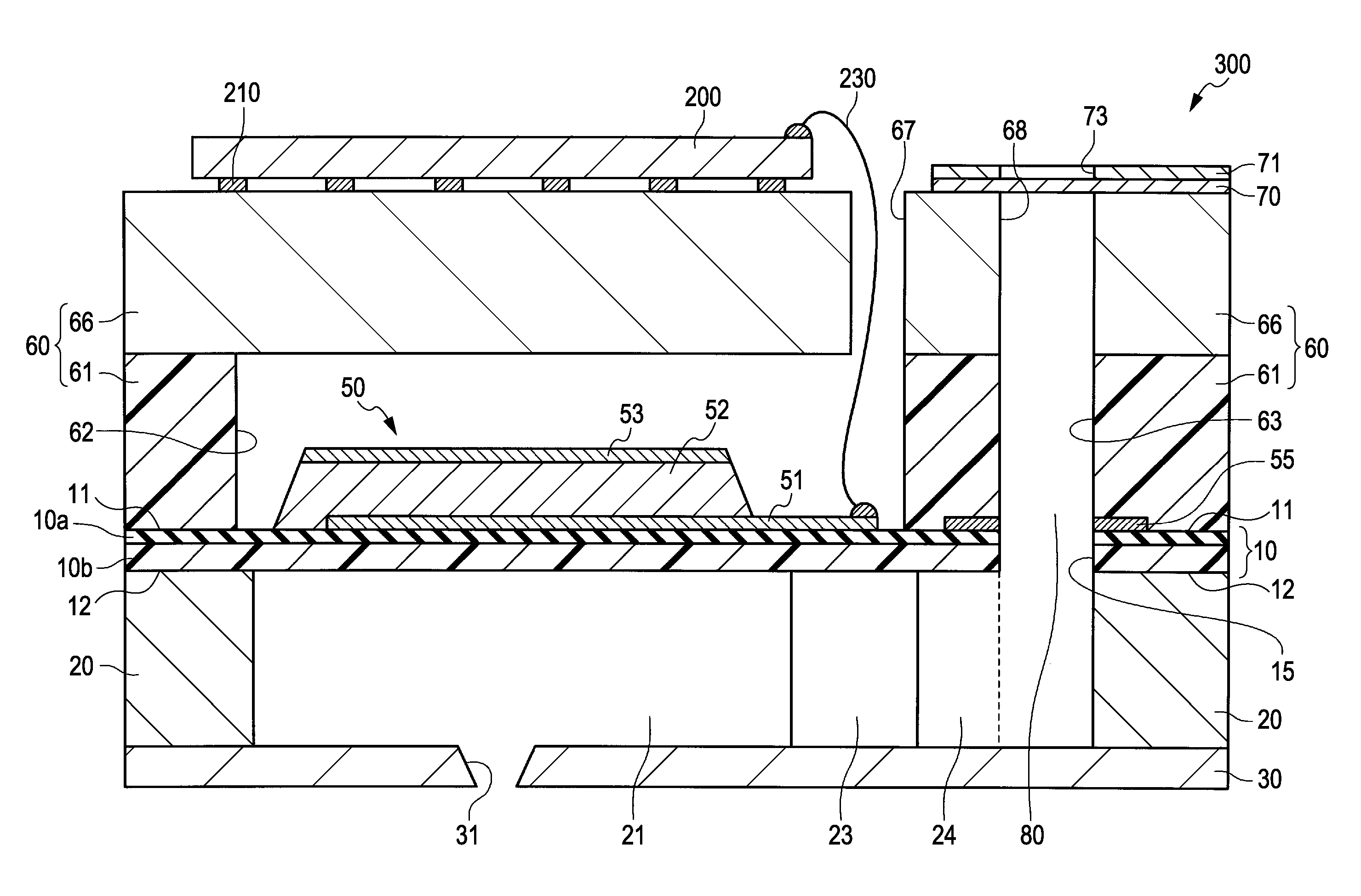
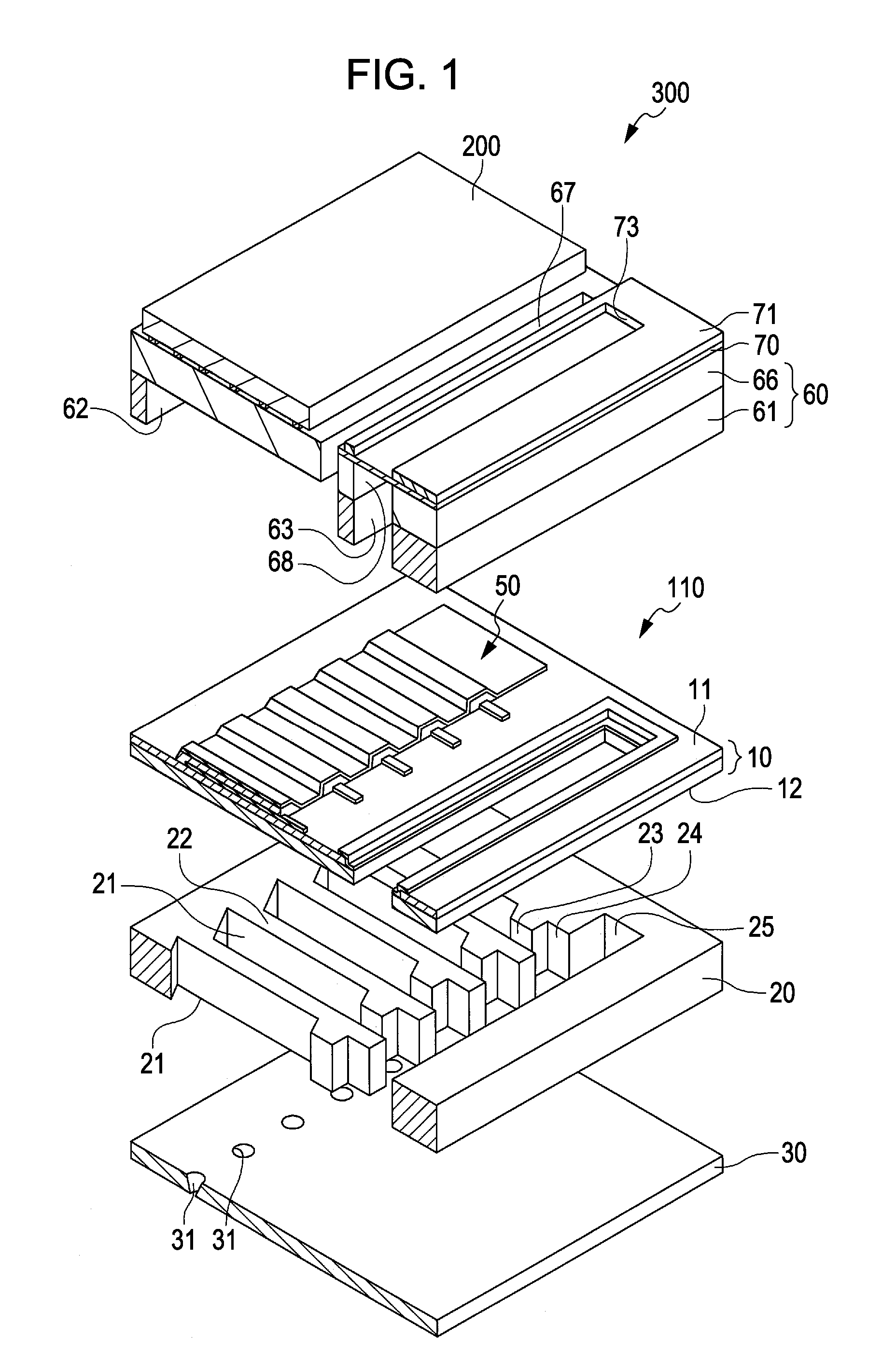
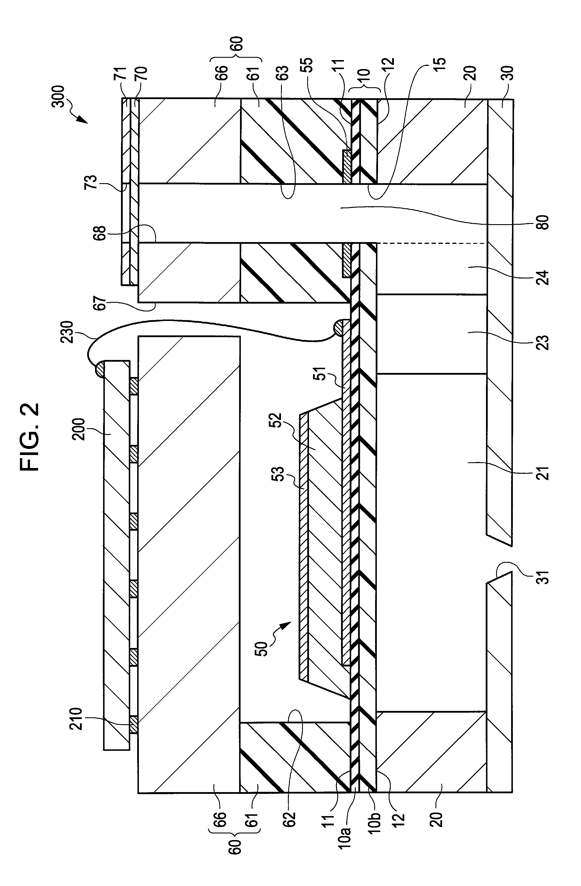
[0044]FIG. 1 is an exploded perspective view schematically showing the liquid droplet ejecting head 300 in accordance with the embodiment. FIG. 2 is a sectional view schematically showing main elements of the liquid droplet ejecting head 300 in accordance with the embodiment. FIGS. 3A and 3B are exploded perspective views schematically showing a support substrate 60 of the liquid droplet ejecting head 300 in accordance with the embodiment.

[0045]As shown in FIGS. 1 and 2, in the liquid droplet ejecting head 300 i...


PUM

PropertyMeasurementUnit
Temperatureaaaaaaaaaa
Thicknessaaaaaaaaaa

Abstract

A liquid droplet ejecting head includes a fluid path forming substrate having a fluid path communicating with nozzle holes and a diaphragm on the fluid path forming substrate. The diaphragm has a first surface facing a second surface. A piezoelectric element on the first surface of the diaphragm has a piezoelectric body layer interposed between a first electrode and a second electrode. A support substrate on the first surface of the diaphragm has a space for containing the piezoelectric element. The support substrate includes a first member formed on the first surface of the diaphragm, and a second member formed on the first member. The first member has a first opening for containing the piezoelectric element. The space of the support substrate is defined by the first opening of the first member and the second member. The main material of the first member is resin.

Description

[0001]This application claims a priority to Japanese Patent Application No. 2009-257816 filed on Nov. 11, 2009 which is hereby expressly incorporated by reference herein in its entirety.BACKGROUND[0002]1. Technical Field[0003]The present invention relates to a liquid droplet ejecting head, a method for manufacturing the same, and a liquid droplet ejecting apparatus.[0004]2. Related Art[0005]For example, in a liquid droplet ejecting apparatus such as an ink jet printer which is available for an image recording apparatus, a display manufacturing apparatus and the like, a piezoelectric element has been extensively used for a liquid droplet ejecting head for ejecting liquid droplets such as ink. In relation to such a piezoelectric element, for example, a piezoelectric body is deformed by the voltage of a driving signal and the like applied thereto, so that a diaphragm formed under the piezoelectric element is deformed, resulting in a change in the volume of a pressure chamber. Thus, the...

Claims


Application Information

Patent Timeline
IPC IPC(8): B41J2/045H04R17/00
CPCB41J2/055B41J2/14233B41J2/161B41J2/1623Y10T29/42B41J2/1626B41J2/1646B41J2002/14241B41J2002/14419B41J2/1625
Inventor FURUYA, NOBORUTAKAKUWA, ATSUSHI
Owner SEIKO EPSON CORP
Learn More