
System and method for detecting casing in a formation using current

Active Publication Date: 2011-05-12
SCHLUMBERGER TECH CORP
View PDF7 Cites 3 Cited by
  • Summary
  • Abstract
  • Description
  • Claims
  • Application Information

AI Technical Summary

Benefits of technology

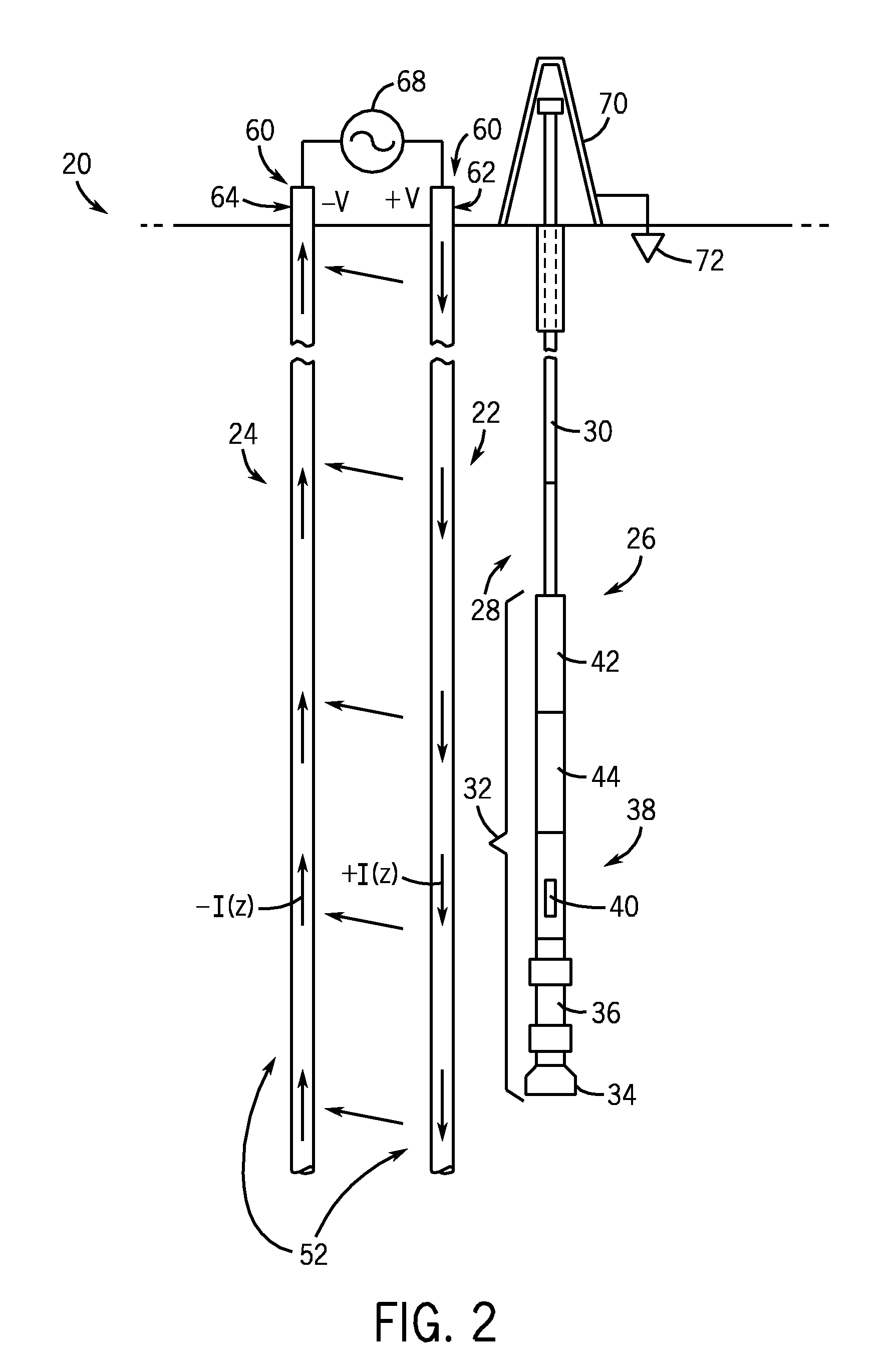
[0008]A system in accordance with exemplary embodiments may include a system for drilling wells in an arrangement relative to one another. Specifically, the system may include a current generator balanced transformer, cable extending from the current generator balanced transformer, wherein the cable is capable of coupling a pair of completed wells with the current generator balanced transformer such that current from the current generator balanced transformer can pass through the pair of completed wells in a current balanced mode, and a drilling tool comprising a magnetometer capable of detecting a direction of a magnetic field produced by the current passing through the pair of completed wells to facilitate calculation of a location of the drilling tool relative to the pair of completed wells.

Problems solved by technology

Such in situ upgrading and conversion processes generally require a large number of heater wells to raise the formation temperature to several hundred degrees C. Indeed, this may require hundreds of heater wells drilled in a dense pattern.
Using many conventional techniques, it may be difficult to accurately drill one well in a specified relationship relative to another well.
Indeed, standard measurement while drilling (MWD) direction and inclination measurements are usually too inaccurate to maintain proper spacing and relative positioning between two wells over a substantial distance.
In part, this is because the location of each well becomes more uncertain as the length of the well increases.
Thus, it may be difficult to accurately position wells relative to one another.
Indeed, if the ellipses for a pair of wells overlap, there is potential for a collision between the wells.

Method used


Image

  • System and method for detecting casing in a formation using current
  • System and method for detecting casing in a formation using current
  • System and method for detecting casing in a formation using current

Examples


Embodiment Construction

[0037]One or more specific embodiments of the present invention are described below. In an effort to provide a concise description of these embodiments, not all features of an actual implementation are described in the specification. It should be appreciated that in the development of any such actual implementation, as in any engineering or design project, numerous implementation-specific decisions must be made to achieve the developers' specific goals, such as compliance with system-related and business-related constraints, which may vary from one implementation to another. Moreover, it should be appreciated that such a development effort might be complex and time consuming, but would nevertheless be a routine undertaking of design, fabrication, and manufacture for those of ordinary skill having the benefit of this disclosure.

[0038]In the following detailed description, reference is made to the accompanying drawings, which form a part hereof, and within which are shown by way of il...


PUM


Abstract

The present disclosure is directed to systems and methods for relative positioning of wells. A method in accordance with an exemplary embodiment may include drilling a new well in a field having at least three completed wells using a drilling tool that includes a magnetometer. The method may further include driving current on a first pair of the at least three completed wells and then driving current on a second pair of the at least three completed wells, wherein the current is driven on each of the first and second pairs in a balanced mode. The method may also include measuring a direction of a first magnetic field generated by the current on the first pair using the magnetometer, measuring a direction of a second magnetic field generated by the current on the second pair using the magnetometer, and determining a location of the drilling tool relative to the completed wells based on the direction of the first magnetic field and the direction of the second magnetic field.

Description

FIELD OF THE INVENTION[0001]The present disclosure relates generally to well drilling operations and, more particularly, to a system and method for drilling a well in a position relative to existing wells using information acquired based on a measurable magnetic field produced via electrical current injected into a formation.BACKGROUND OF THE INVENTION[0002]In order to access certain types of hydrocarbons in the earth, it may be necessary or desirable to drill wells or boreholes in a certain spatial relationship with respect to one another. Producing unconventional oil such as shale oil, heavy oil, or bitumen, may require technology that utilizes an arrangement of boreholes. For example, heavy oil may be too viscous in its natural state to be produced from a conventional well, and, thus, an arrangement of cooperative wells and well features may be utilized to produce such oil. Indeed, to produce certain types of unconventional oil, it may be desirable to drill numerous boreholes in ...

Claims


Application Information

Patent Timeline
IPC IPC(8): G01V3/08
CPCE21B47/022
Inventor CLARK, BRIANMORLEY, JAN S.
Owner SCHLUMBERGER TECH CORP
Learn More