Frequency control circuit and method for a non-constant frequency voltage regulator

Inactive Publication Date: 2011-05-12
RICHTEK TECH
View PDF2 Cites 12 Cited by
  • Summary
  • Abstract
  • Description
  • Claims
  • Application Information

AI Technical Summary

Benefits of technology

[0009]In the present invention, the pulse width of a phase node voltage is detected in order to compensate for the operating frequency of a voltage regulator and thereby reduce frequency error resulting from the deadtime.

Problems solved by technology

If a PWM power converter uses a non-fixed frequency system architecture, such as a constant on-time or constant off-time control system, the frequency of the PWM power converter may deviate from the designed value under different loading and cause new problems.
U.S. Pat. No. 6,774,611 uses a phase locked loop (PLL) to control the duty cycle of the PWM signal and thus provide precise frequency control, but the circuit is highly complicated.

Method used


Image

  • Frequency control circuit and method for a non-constant frequency voltage regulator
  • Frequency control circuit and method for a non-constant frequency voltage regulator
  • Frequency control circuit and method for a non-constant frequency voltage regulator

Examples


Embodiment Construction

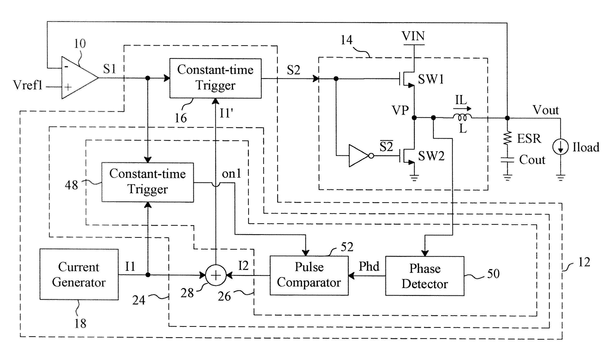
[0022]FIG. 5 is a circuit diagram of an embodiment according to the present invention, in which the PWM signal generator 12 includes a frequency control circuit 24 in addition to the constant-time trigger 16 and the current generator 18. The frequency control circuit 24 adjusts the first current I1 supplied to the constant-time trigger 16 to be a current I1′ for frequency compensation to the PWM signal S2. In the frequency control circuit 24, a compensator 26 generates a second current I2 and an adder 28 adds the second current I2 to the first current I1 to generate the current I1′. In the compensator 26, responsive to the comparison signal S1, a constant-time trigger 48 triggers a constant on-time Ton or a constant off-time Toff whose width is set by the current I1 provided by the current generator 18, just the same as the constant-time trigger 16 shown in FIG. 1, and thus the reference signal on1 generated by the constant-time trigger 48 contains the constant on-time Ton or the co...


PUM


Abstract

A non-constant frequency voltage regulator includes a constant-time trigger to generate a pulse width modulation signal, a current generator to provide a first current to set a constant on-time or a constant off-time for the pulse width modulation signal, and a frequency control circuit to detect the pulse width of a phase node voltage, compare the pulse width with the constant on-time or the constant off-time set by the first current to generate a second current, and add the second current to the first current to supply to the constant-time trigger to control the frequency of the pulse width modulation signal.

Description

FIELD OF THE INVENTION[0001]The present invention is related generally to a non-constant frequency voltage regulator and, more particularly, to a frequency control circuit and method for a non-constant frequency voltage regulator.BACKGROUND OF THE INVENTION[0002]If a PWM power converter uses a non-fixed frequency system architecture, such as a constant on-time or constant off-time control system, the frequency of the PWM power converter may deviate from the designed value under different loading and cause new problems. For example, two channels on a printed circuit board (PCB) are designed to operate with a frequency difference of higher than 100 KHz therebetween, but the real operation frequencies of the two channels may quite close to each other under certain loading, thereby causing audio beating. FIG. 1 is a circuit diagram of the basic architecture for constant on-time and constant off-time PWM, and FIG. 2 is a waveform diagram thereof. Referring to FIGS. 1 and 2, a comparator ...

Claims


Application Information

Patent Timeline
IPC IPC(8): G05F1/10
CPCH02M3/156
Inventor TANG, CHIEN-FUCHEN, ISAAC Y.
Owner RICHTEK TECH
Why Eureka
Try Eureka