Manual control device with power generation function and remote control device with power generation function
- Summary
- Abstract
- Description
- Claims
- Application Information
AI Technical Summary
Benefits of technology
Problems solved by technology
Method used
Image
Examples
first exemplary embodiment
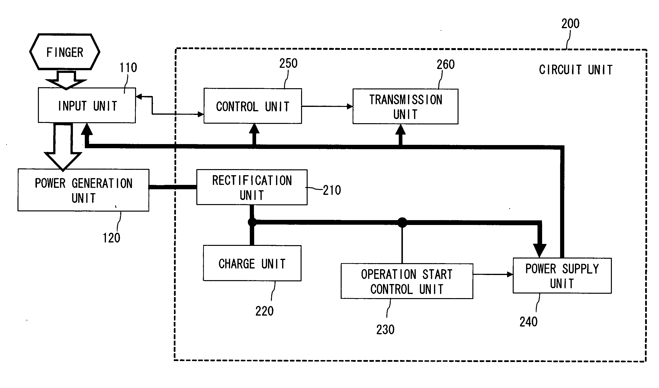
[0043]FIG. 1 illustrates a configuration of a remote control device (manual control device) 100 according to a first exemplary embodiment.
[0044]The remote control device 100 includes an input unit 110, a power generation unit 120, and a circuit unit 200.
[0045]The input unit 110 is a touch sensor type input device.
[0046]The configuration of the touch sensor is not especially limited, as long as it is a sheet-like touch sensor that can detect a region touched by a user finger.
[0047]A plurality of buttons 111 are printed on a surface part of the touch sensor.
[0048]A letter, a symbol, or the like are placed to each button 111. Each button 111 corresponds to a predetermined command.
[0049]Note that the button 111 here simply means a mark indicating a region corresponding the command, and does not mean a physical switch device that functions as a detection device.
[0050]The power generation unit 120 converts applied force into voltage.
[0051]The power generation unit 120 includes a piezoelec...
modification 1
(Modification 1)
[0110]A modification 1 is explained hereinafter.
[0111]FIG. 5 illustrates the modification 1.
[0112]In the above first exemplary embodiment, the touch sensor input unit 110 and the circuit unit 220 are arranged to the top surface side of the power generation unit 120.
[0113]On the other hand, in the modification 1, the circuit unit 200 is arranged to the side surface side of the power generation unit 120, and the entire top surface of the power generation unit 120 is a region to arrange the input unit 110.
[0114]As the entire top surface of the power generation unit 120 can be the input unit 110, the button 111 can be placed to the central region of the power generation unit 120.
[0115]Thus, the central region of the power generation unit 120 is pressed harder at the time of button operation by a user, and thereby further increasing the amount of deformation of the power generation unit 120. Accordingly, a greater amount of electric power generation can be obtained.
modification 2
(Modification 2)
[0116]The touch sensor type input unit 110 may be formed of flexible material, such as a resin film.
[0117]In such case, if the user presses the touch sensor input unit 110, both the touch sensor input unit 110 and the power generation unit 120 bend and deform as shown in FIG. 6.
[0118]If the button 111 is placed to the central region, little pressure is needed to bend and largely deform the power generation unit 120.
[0119]Alternatively, as illustrated in FIG. 7, plate material 112 having stiffness such as an organic glass and a plastic plate may be arranged to the bottom surface of the touch sensor type input unit 110.
[0120]In such a case, when the user presses the touch sensor input unit 110 with a finger, the entire plate material 112 presses down the power generation unit 120. Thus the power generation unit 120 shrinks as compressed from above.
[0121]As the plate material 112 evenly presses down the top surface of the power generation unit 120, the power generation ...
PUM
 Abstract
Description
Claims
Application Information
 - R&D
- Intellectual Property
- Life Sciences
- Materials
- Tech Scout
- Unparalleled Data Quality
- Higher Quality Content
- 60% Fewer Hallucinations
Browse by: Latest US Patents, China's latest patents, Technical Efficacy Thesaurus, Application Domain, Technology Topic, Popular Technical Reports.
© 2025 PatSnap. All rights reserved.Legal|Privacy policy|Modern Slavery Act Transparency Statement|Sitemap|About US| Contact US: help@patsnap.com


