
Pro fencer brace system

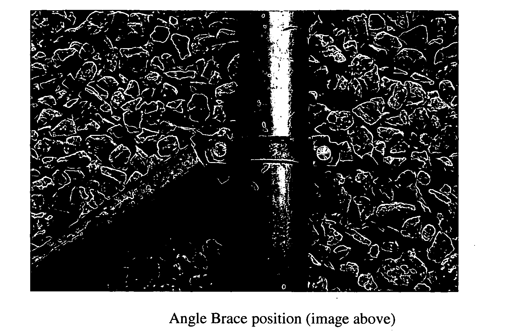
Inactive Publication Date: 2011-05-12
BULLOCK CHARLES L +1
View PDF9 Cites 0 Cited by
  • Summary
  • Abstract
  • Description
  • Claims
  • Application Information

AI Technical Summary

Benefits of technology

[0001]The invention known as “PRO FENCER BRACE SYSTEM” is unique in it's configuration and design. It was developed to be more flexible and lower cost in application than previous systems. It is capable of multiple applications as a bracing support component for commercial, residential, game and security fencing.

Problems solved by technology

2) Prior Art bracing fixtures are cast at fixed angles which limit the way that fences can be configured in rugged terrain.

Method used


Image

  • Pro fencer brace system
  • Pro fencer brace system
  • Pro fencer brace system

Examples


Embodiment Construction

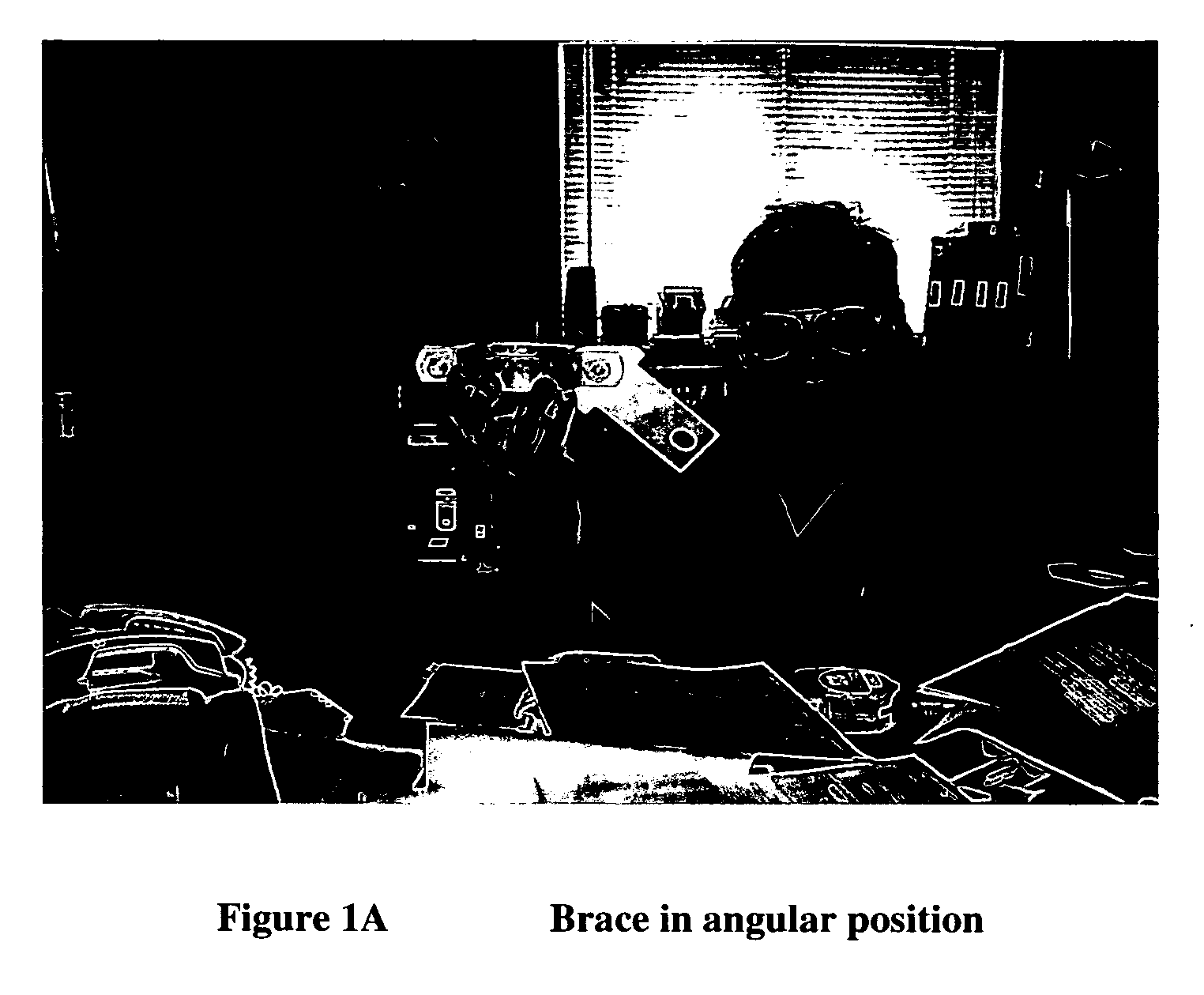
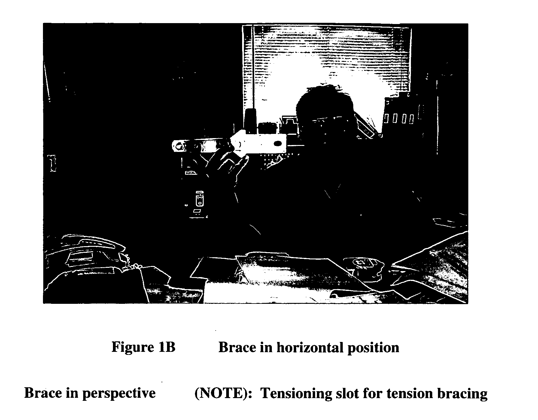
[0013]The Pro Fencer Brace System consists of a “Post Clamp” and a “Horizontal and / or Angular Support insert”, whereas the “Support Insert” is unique and previously did not exist.

[0014]“The Post Clamp” is a common hardware item used in commercial and residential fencing composed of ¼″ to ½″ metal plate material shaped to fit in pairs around a 2″ to 6″ metal fence pipe or wood post with holes on both sides to accommodate bolts to immobilize said post or pipe. This allows the support insert to be pivoted 360°

[0015]The “Horizontal and / or Angular Support Insert” is a unique device used to create a support connection that can be used as a “compression” or push type of support or it can be used as a “tension” or pull type support. It is made by punch pressing or cutting ¼″ to ½″ extruded metal in the unique “arrow” shape or mushroom shape, thus accommodating multiple angles of usefulness in uneven terrains encountered in fence building. Two ⅜″ slots are machined or punched to allow for th...


PUM


Abstract

The “Pro Fencer Brace System” is basically a metal insert and clamp that act as a multi-angular receiver for compression or tension bracing on game or livestock fencing.

Description

BRIEF SUMMARY OF THE INVENTION[0001]The invention known as “PRO FENCER BRACE SYSTEM” is unique in it's configuration and design. It was developed to be more flexible and lower cost in application than previous systems. It is capable of multiple applications as a bracing support component for commercial, residential, game and security fencing.[0002]To use the “Pro Fencer Brace” in the angular position, you first set 2″ to 6″ wood or metal posts 2-4 ft. in the ground, secure the post base and fasten a “Pro Fencer” clamp, insert approximately at the point that is 75% of the total height of the post and one at approximately 6″ from the ground on the next post. Measure and cut a section of approximately 2″ pipe material to fit on the two opposing tabs of the inserts and loosen the-top Pro Fencer clamp enough to slide it so that the pipe that was cut to fit will slide onto the two opposing insert tabs. Then slide the top Pro Fencer clamp down to remove any slack and tighten clamp. You now...

Claims


Application Information

Patent Timeline
IPC IPC(8): F16L3/08F16M13/02F16M13/00
CPCF16L3/1091A01K3/00
Inventor BULLOCK, CHARLES L.STACK, IV, JOE "CUATRO"
Owner BULLOCK CHARLES L
Learn More