
Path planning apparatus of robot and method and computer-readable medium thereof

a technology of path planning and robots, applied in the direction of programme control, hybrid vehicles, electric programme control, etc., can solve the problems of reduced convergence speed, unsatisfactory constraints, repetitive tasks or performed tasks requiring a large amount of force, etc., and achieve the effect of improving the path planning performan

Active Publication Date: 2011-05-05
SAMSUNG ELECTRONICS CO LTD
View PDF11 Cites 41 Cited by
  • Summary
  • Abstract
  • Description
  • Claims
  • Application Information

AI Technical Summary

Benefits of technology

Therefore, it is an aspect of the example embodiments to provide a path planning apparatus of a robot which improves path planning performance by planning a path based on a sample which considers a dynamic constraint, and a method and computer-readable medium thereof.
The dynamic stability of the robot may be satisfied by enabling the COG and the ZMP of the robot to fall within the supporting polygon to maintain balance of the robot.
According to an apparatus, method and computer-readable medium planning a path of a robot, in a process of searching for a motion path from a start point to a goal point while extending a tree in a configuration space in which a manipulator of the robot performs a task, an optimal path is generated responsive to a dynamic constraint of the manipulator of the robot to generate stable motion satisfying momentum and Zero Moment Position (ZMP) constraint. Accordingly, path planning performance is improved and a path satisfying a kinematic constraint and a dynamic constraint is rapidly obtained.

Problems solved by technology

Robots also performed dangerous tasks, repetitive tasks or performed tasks requiring a large amount of force.
However, since this method does not consider time, a convergence speed is decreased if a dimension is increased.
In addition, in a dynamic state where speed or balance is important, a constraint is not satisfied.

Method used


Image

  • Path planning apparatus of robot and method and computer-readable medium thereof
  • Path planning apparatus of robot and method and computer-readable medium thereof
  • Path planning apparatus of robot and method and computer-readable medium thereof

Examples


Embodiment Construction

Reference will now be made in detail to the embodiments, examples of which are illustrated in the accompanying drawings, wherein like reference numerals refer to like elements throughout.

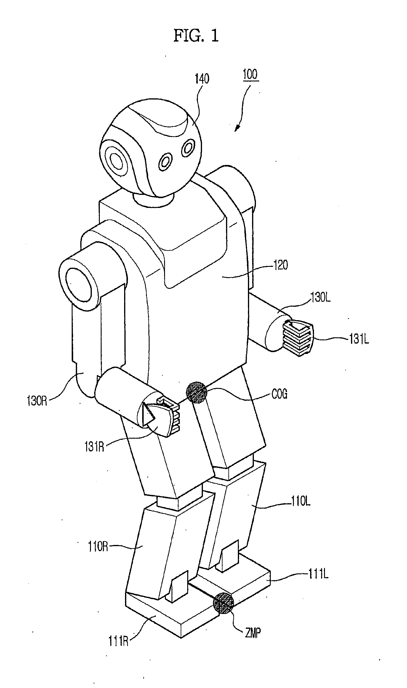
FIG. 1 is an appearance view showing an example of a robot according to example embodiments.

In FIG. 1, the robot 100 according to example embodiments is a bipedal robot which walks erect using two legs 110R and 110L similar to a human, and includes a trunk 120, two arms 130R and 130L and a head 140 mounted on an upper side of the trunk 120, and feet 111R and 111L and hands 131R and 131L respectively mounted on the front ends of the two legs 110R and 110L and the arms 130R and 130L.

In the reference numerals, R and L denote right and left, respectively. A Center Of Gravity (COG) denotes a center of gravity of the robot 100, and a Zero Moment Position (ZMP) denotes a point where moment of a roll direction (an x-axis direction which is a walking direction of the robot) and a pitch direction (a y-axis di...


PUM


Abstract

An apparatus, method and computer-readable medium planning a path of a robot by planning an optimal path while satisfying a dynamic constraint. In a process of searching for a motion path from a start point to a goal point while extending a tree from a start point of a configuration space to generate a path, along which a manipulator of the robot is moved in order to perform a task, an optimal path is generated responsive to the dynamic constraint of the manipulator of the robot to generate stable motion satisfying momentum and Zero Moment Position (ZMP) constraint. Accordingly, path planning performance is improved and a path satisfying a kinematic constraint and a dynamic constraint is rapidly obtained.

Description

CROSS-REFERENCE TO RELATED APPLICATIONSThis application claims the benefit of Korean Patent Application No. 2009-0104627, filed on Oct. 30, 2009 in the Korean Intellectual Property Office, the disclosure of which is incorporated herein by reference.BACKGROUND1. FieldExample embodiments relate to a path planning apparatus planning an optimal path while satisfying a dynamic constraint, and a method and computer-readable medium thereof.2. Description of the Related ArtIn general, a mechanical device which performs motion similar to human motion using an electrical or magnetic mechanism is called a robot. Early robots included manipulators used for automated or unmanned tasks in manufacturing plants or industrial robots such as transportation robots. Robots also performed dangerous tasks, repetitive tasks or performed tasks requiring a large amount of force. Recently, research into a humanoid robot, which has joints similar to those of a human, and coexists with a human in a working and...

Claims


Application Information

Patent Timeline
IPC IPC(8): G05B19/04B25J9/06
CPCB25J9/1666G05B2219/40264G05D2201/0217G05D1/0214G05B2219/40517B25J5/00B25J9/10B25J9/1664B25J13/08B60W20/12G05B2219/40515
Inventor KIM, MYUNG HEELIM, BOK MANROH, KYUNG SHIKLIM, SAN
Owner SAMSUNG ELECTRONICS CO LTD
Learn More