
Accelerator-pedal reaction force control apparatus

Active Publication Date: 2011-04-28
NISSAN MOTOR CO LTD
View PDF6 Cites 17 Cited by
  • Summary
  • Abstract
  • Description
  • Claims
  • Application Information

AI Technical Summary

Benefits of technology

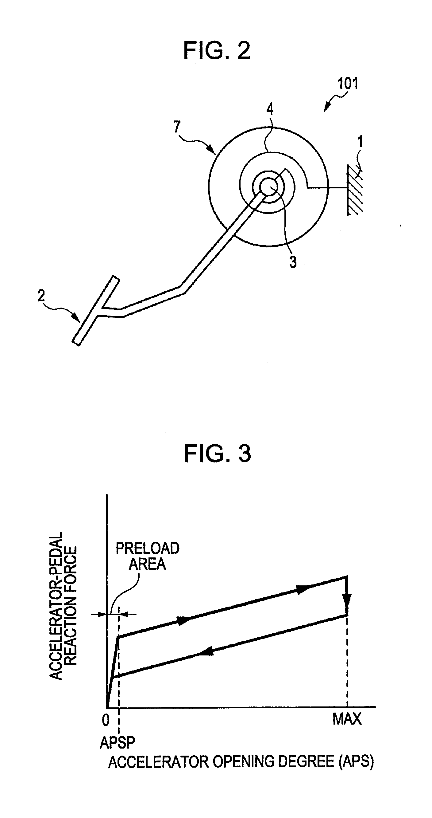
[0010]In one aspect, the present disclosure relates to an accelerator control apparatus of a vehicle including a means for detecting a position of an accelerator, a means for adjusting a reaction force of the accelerator, the accelerator configured to receive a basic reaction force which increases as an accelerator opening degree increases, and wherein the means for adjusting increases the reaction force of the accelerator by an increase amount in addition to the basic reaction force when the position of the accelerator is increased to satisfy a predetermined condition associated with a specific fuel consumption of the vehicle, wherein the means for adjusting sets the increase amount to a first amount when the position of the accelerator is increased from a first accelerator position in a preload area to a second accelerator position that satisfies the predetermined condition, wherein the means for adjusting sets the increase amount to a second amount when the position of the accelerator is increased from an intermediate accelerator position that exceeds the preload area to the second position, and wherein the first amount is greater than the second amount.
[0011]In another aspect, the present disclosure relates to an accelerator control apparatus including a vehicle accelerator receiving a basic reaction force increasing as a position of the vehicle accelerator increases, a means for detecting the position of the accelerator, a means for adjusting a reaction force of the accelerator, and wherein the means for adjusting increases the reaction force of the accelerator from the basic reaction force when the position of the accelerator is increased to satisfy a predetermined condition that is associated with a specific fuel consumption of the vehicle, wherein the basic reaction force increases from a first position of the accelerator to a second position of the accelerator at a second rate of force increase when the position of the accelerator is increased, wherein the basic reaction force increases at a first rate of force increase which is larger than the second rate of force increase in accordance with an increase in the position of the accelerator from a zero position to the first position, and wherein the means for adjusting increases the reaction force by a second amount from the basic reaction force when the position of the accelerator is increased from an intermediate accelerator position that is larger than the first position to a position that satisfies the predetermined condition, and by a first amount when the position of the accelerator is increased from the position that is equal to the zero position or less than the first position to the position that satisfies the predetermined condition, the first amount being larger than the second amount.
[0012]In another aspect, embodiments disclosed herein relate to a method to control an accelerator of a vehicle including detecting a position of an accelerator, adjusting a reaction force of the accelerator, applying a basic reaction force to the accelerator which increases as an accelerator opening degree increases, and increasing the reaction force of the accelerator by an increase amount in addition to the basic reaction force when the position of the accelerator is increased to satisfy a predetermined condition associated with a specific fuel consumption of the vehicle, setting the increase amount to a first amount when the position of the accelerator is increased from a first accelerator position to a

Problems solved by technology

However, the accelerator pedal is a main operating member operated by the driver to drive the vehicle in a way that the driver desires, and the operational feel of the accelerator pedal experienced by the driver is extremely delicate.
For this reason, this type of reaction-force control apparatus, which contributes to the reduction in fuel consumption, cannot be put into practical use unless the function for reducing the fuel consumption can be achieved together with satisfactory operational feel of the accelerator pedal.
For example, it is generally more difficult for the driver to recognize the change in force required to depress the accelerator pedal when the reaction force is increased by the same amount at the same accelerator opening degree in the case in which the accelerator opening degree is increased from an intermediate accelerator opening degree as well as the case in which the accelerator opening degree is increased from 0 degrees, such as in the case where the vehicle is started running from a stopped state.
Therefore, there is a risk that the optimum amount of operation cannot be recognized by the driver.

Method used


Image

  • Accelerator-pedal reaction force control apparatus
  • Accelerator-pedal reaction force control apparatus
  • Accelerator-pedal reaction force control apparatus

Examples


Embodiment Construction

[0028]Exemplary embodiments of the present disclosure will be described in detail below with reference to the drawings.

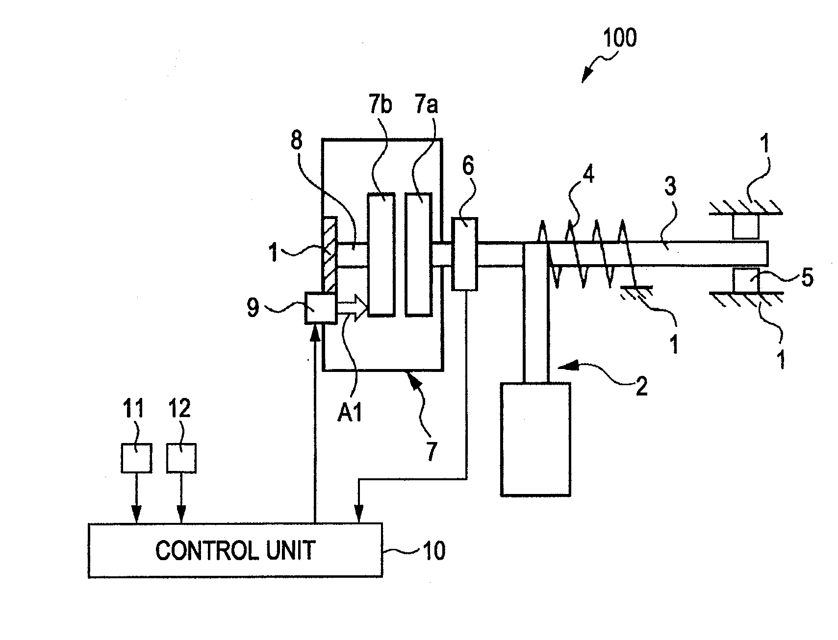
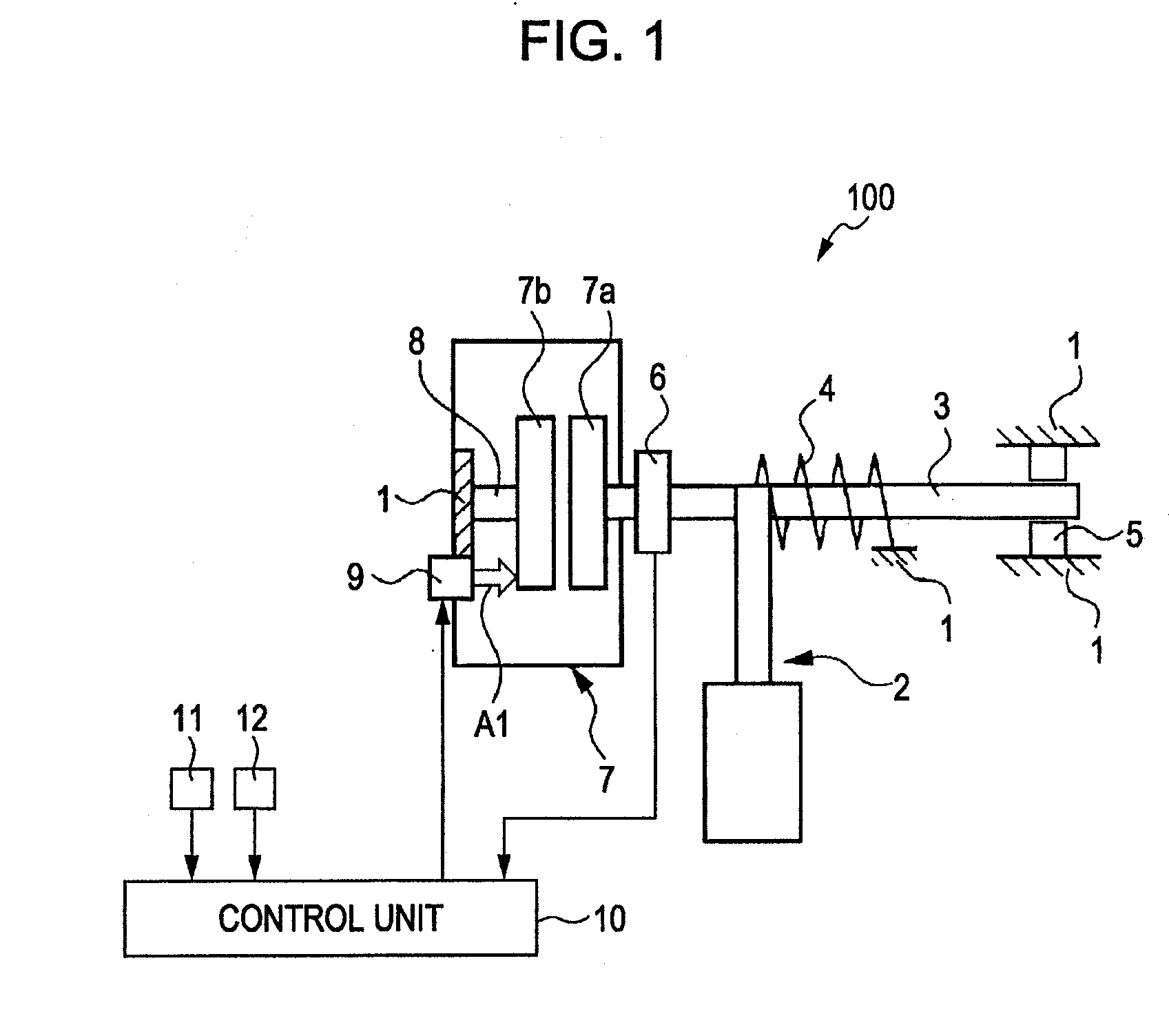
[0029]FIG. 1 is a schematic diagram illustrating the system structure of an accelerator-pedal reaction force control apparatus 100. An accelerator-pedal reaction force control apparatus 100 may control a reaction force (operational reaction force) of an accelerator pedal 2 provided in a vehicle body 1 of a vehicle (not shown). While the term “accelerator pedal” or “accelerator” is used throughout this specification, it should be understood that such terms should not be limited to any particular embodiment or style of input device. In particular, while a “pedal” inside the passenger compartment is described, it should be understood that the “accelerator” may be a device in the engine compartment responsive to electrical, hydraulic, or mechanical signals produced by a pedal (or other device) in the passenger compartment. Additionally, while the device in the passenger...


PUM


Abstract

A control apparatus includes a means for detecting a position and a means for adjusting a reaction force of the accelerator, wherein the means for adjusting increases the reaction force of the accelerator by an increase amount in addition to a basic reaction force when the position of the accelerator is increased to satisfy a predetermined condition associated with a specific fuel consumption of the vehicle, the means for adjusting sets the increase amount to a first amount when the position of the accelerator is increased from a first accelerator position in a preload area to a second accelerator position that satisfies the predetermined condition, the means for adjusting sets the increase amount to a second amount when the position of the accelerator position is increased from an intermediate accelerator position that exceeds the preload area to the second position, and the first amount is greater than the second amount.

Description

CROSS-REFERENCE TO RELATED APPLICATIONS[0001]The present application claims priority from Japanese Patent Application No. 2008-197387, filed Jul. 31, 2008 and Japanese Patent Application No. 2009-123002, filed May 21, 2009. The contents of both priority applications are hereby incorporated by reference in their entirety.BACKGROUND OF THE DISCLOSURE[0002]1. Field of the Disclosure[0003]The present disclosure relates to an accelerator-pedal reaction force control apparatus which controls a reaction force of an accelerator pedal.[0004]2. Description of the Related Art[0005]Japanese Unexamined Patent Application Publication No. 2007-76468 (hereinafter referred to as Patent Document 1) discloses a technique for allowing a driver to recognize an optimum amount of operation of an accelerator pedal by increasing an operation reaction force (hereinafter simply referred to as a reaction force) of the accelerator pedal stepwise at the optimum amount of operation of the accelerator pedal, that ...

Claims


Application Information

Patent Timeline
IPC IPC(8): G05G5/03G06F19/00
CPCF02D11/02B60K26/021B60K26/04F02D11/04
Inventor SHIOMI, MASAOSAKAGUCHI, SHIGEYUKI
Owner NISSAN MOTOR CO LTD
Learn More