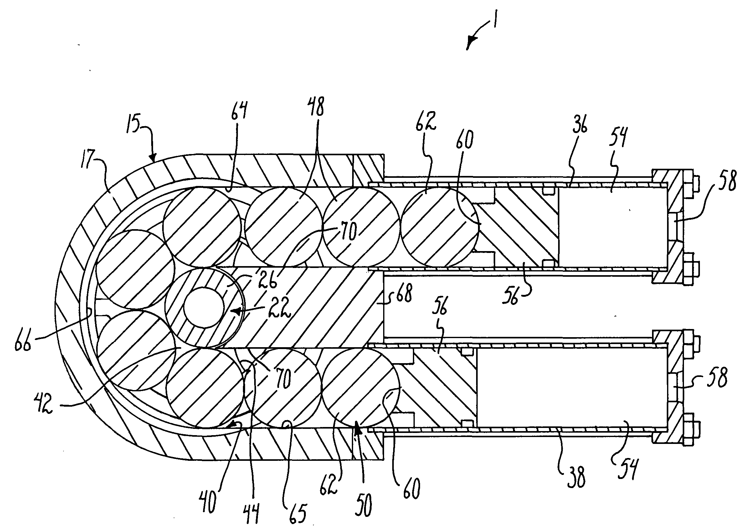
Ball and piston rotary actuator mechanism
a rotary actuator and piston technology, applied in the direction of programmable manipulators, gearing, joints, etc., can solve the problems of limiting the range of motion of the attached arm, prone to damage, and rotary stroke less than 360 degrees
- Summary
- Abstract
- Description
- Claims
- Application Information
AI Technical Summary
Benefits of technology
Problems solved by technology
Method used
Image


Examples
Embodiment Construction
[0026]As required, detailed embodiments of the present invention are disclosed herein; however, it is to be understood that the disclosed embodiments are merely exemplary of the invention, which may be embodied in various forms. Therefore, specific structural and functional details disclosed herein are not to be interpreted as limiting, but merely as a basis for the claims and as a representative basis for teaching one skilled in the art to variously employ the present invention in virtually any appropriately detailed structure.
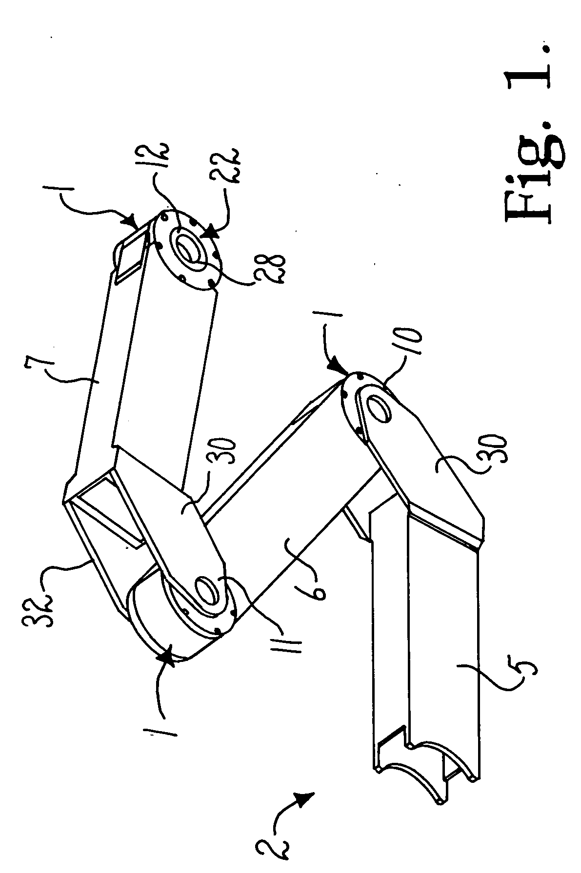
[0027]Referring to the drawings in more detail, the reference numeral 1 (in FIGS. 1-11) generally designates an embodiment of a ball and piston rotary actuator mechanism according to the present invention. The mechanism 1 is controlled to cause relative pivoting between structures interconnected by the mechanism 1, such as between components of a robotic arm assembly 2 (FIG. 1).
[0028]The illustrated robotic arm assembly 2 includes a base link or base 5 to whi...
PUM
 Abstract
Description
Claims
Application Information
 - R&D
- Intellectual Property
- Life Sciences
- Materials
- Tech Scout
- Unparalleled Data Quality
- Higher Quality Content
- 60% Fewer Hallucinations
Browse by: Latest US Patents, China's latest patents, Technical Efficacy Thesaurus, Application Domain, Technology Topic, Popular Technical Reports.
© 2025 PatSnap. All rights reserved.Legal|Privacy policy|Modern Slavery Act Transparency Statement|Sitemap|About US| Contact US: help@patsnap.com