
Center Draper Belt With Crop Conveying Features

Inactive Publication Date: 2011-04-28
DEERE & CO
View PDF29 Cites 17 Cited by
  • Summary
  • Abstract
  • Description
  • Claims
  • Application Information

AI Technical Summary

Benefits of technology

What is needed, therefore, is an improved center conveyor belt for draper platform that better engages the bottom layer of the crop mat and more effectively turns it from its lateral flow direction to a rearward flow direction. It is also an object of this invention to provide belting for making an endless belt for a center conveyor that solves this problem. It is also an object of this invention to provide an improved endless belt and center conveyor using such an endless belt. It is also an object of this invention to provide an improved draper platform having such a center conveyor.
The function of the crop arresting structures for center draper belts in the present application is to halt the crop mat as it travels across the center conveyor at the conveyor loading location, to prevent only the material in the bottom layer of the crop mat from being pulled into a gap between the side conveyor and the center conveyor, and to prevent the intertwined fibers of the plant stalks in the bottom layer from pulling a stream of adjacent plant stalks out from the bottom of the crop mat deposited on center conveyor.

Problems solved by technology

Unfortunately, the width of the center conveyor cannot be substantially increased to carry this increased volume of cut crop.
A side-to-side imbalance in the volume of crop flow (e.g. the left side conveyor having a crop mat of much greater thickness than the right side conveyor or vice versa) causes the two crop mats to no longer collide in the center of the draper platform.
The plant stalks dragged into this gap fall on the ground and are lost.
The problem to be solved is that of underfeeding the bottom layer of a crop mat composed of interengaging plant stalks into a gap between a center conveyor and an overlying and spaced apart upper conveyor.
These conveyors face the problem of containing the material as it is jostled, spreads and settles.
Second, fluent material must be contained by walls that extend upward higher than the maximum operating height of the material carried by the conveyor belt.
Third, fluent material conveyors are provided with sidewalls to contain material that flows out under the force of gravity, not to provide a barrier between the conveyed material and an adjacent apparatus that will pull the conveyed material out of the center conveyor.

Method used


Image

  • Center Draper Belt With Crop Conveying Features
  • Center Draper Belt With Crop Conveying Features
  • Center Draper Belt With Crop Conveying Features

Examples


Embodiment Construction

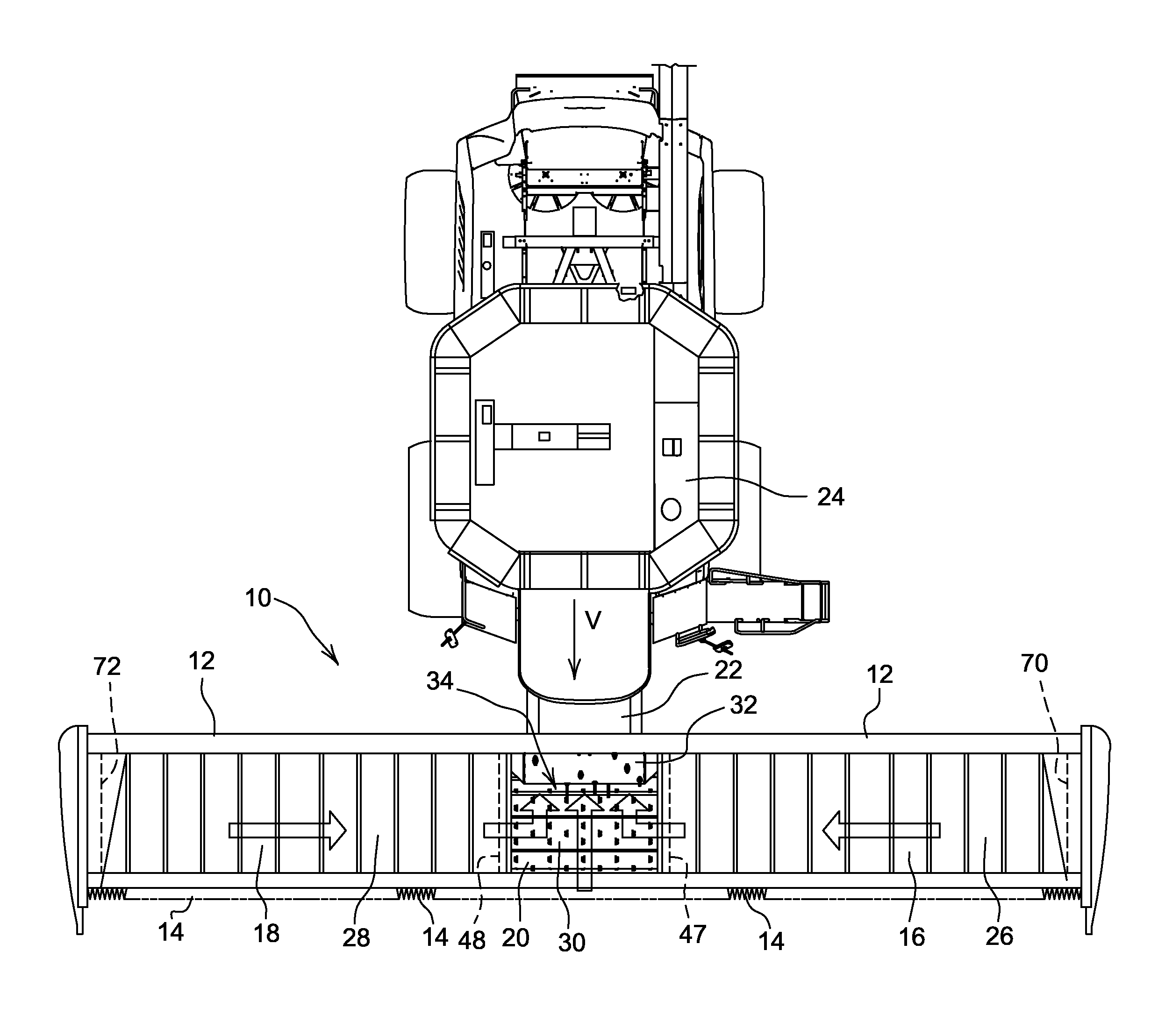
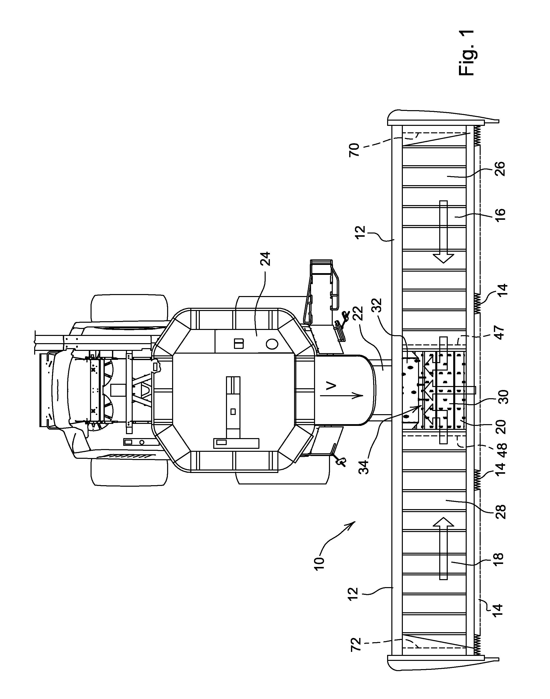
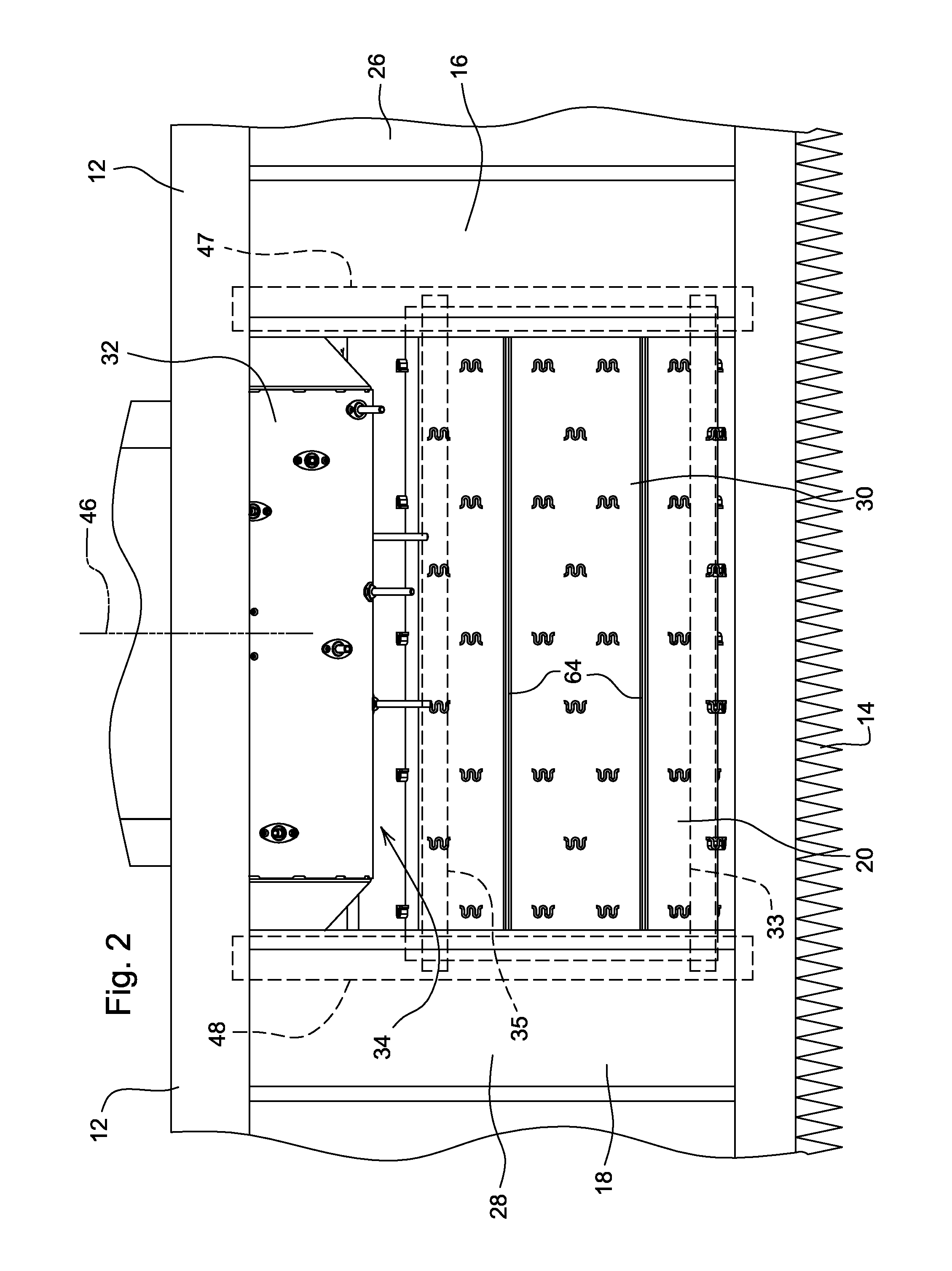
In FIGS. 1 and 2, a draper platform 10 is shown having a frame 12, a reciprocating knife 14 disposed along a leading edge of frame 12, two left side and right side conveyors 16, 18, and center conveyor 20. Draper platform 10 is supported on a feederhouse 22, which in turn is supported on the front of a combine 24.

In operation, combine 24 drives through an agricultural field in the direction of travel indicated by the arrow “V” in FIG. 1, conveying the draper platform in a direction generally perpendicular to its longitudinal extent. Reciprocating knife 14 located along the leading edge of draper platform 10 engages the plant stalks, severing them from the ground and causing them to fall rearward on to the left side conveyor 16, center conveyor 20, and right side conveyor 18. Each of the three conveyors 16, 18, 20 has an endless belt 26, 28, 30, respectively. Each of endless belts 26, 28, 30 provides a generally flat surface to support the crop and move in a direction indicated by th...


PUM


Abstract

A center draper belt for a center conveyor of a draper platform that is configured to carry a crop mat of severed plant stalks in a first direction, the crop mat having a maximum operating thickness, the belt comprises a generally planar web having first and second longitudinally side edges disposed on opposite sides of the web; and first and second ridges fixed to the longitudinal side edges and extending upward therefrom to stop plant stalks of a bottom layer of the crop mat from being propelled off the side edges.

Description

FIELD OF THE INVENTIONThe invention relates to agricultural harvesters. More particularly, it relates to draper platforms for agricultural harvesters. Even more particularly, it relates to the construction of center draper belts for draper platforms.BACKGROUND OF THE INVENTIONDraper platforms are harvesting heads supported on the front of self-propelled agricultural combine vehicles (hereinafter “combine”). They are configured to cut the stalks of crop plants, severing them from the ground, to direct the crop plant onto endless belt side conveyors to form a thick crop mat. The side conveyors convey their respective crop mats laterally from either side of the center conveyor toward a center conveyor. The center conveyor, in turn, receives the crop mats, combines them and redirects their flow ninety degrees from a lateral direction of travel to a rearward direction. The center conveyor carries the now-combined crop mats rearward toward an aperture in the draper platform frame. Once th...

Claims


Application Information

Patent Timeline
IPC IPC(8): A01D43/00
CPCA01D61/02
Inventor BOMLENY, DUANEDEMAY, TERRYCONRAD, WILLIAM PAYNESIGNER, TODD NEIL
Owner DEERE & CO
Learn More