Z-pinch plasma generator and plasma target

a plasma generator and plasma target technology, applied in plasma technique, electric discharge tubes, light sources, etc., can solve problems such as inability to achieve dielectric barriers

Inactive Publication Date: 2011-04-21
PUREX
View PDF25 Cites 15 Cited by
  • Summary
  • Abstract
  • Description
  • Claims
  • Application Information

AI Technical Summary

Benefits of technology

[0006]Typically the final diameter of the compressed Z-pinch plasma is less than 1 mm, but for effective laser excitation and subsequent transport of the emitted radiation via an optical system the lateral position of the compressed plasma must remain constant in space to within a small fraction of 1 mm. The positional stability of a Z-pinch is primarily determined by the exact cylindrical symmetry of the low density start plasma. We disclose an electrode configuration that provides a very symmetrical hollow cylinder of low density plasma. A further electrode configuration provides for a central cool, dense “core” plasma target surrounded by a hot “liner” plasma which compresses the core.
[0007]According to a first aspect of the invention, a configuration comprises two opposed electrodes with conical depressions on

Problems solved by technology

In addition, a dielectric barrier is not possible when lithium is used as the working gas because of chemical reactivity.

Method used


Image

  • Z-pinch plasma generator and plasma target
  • Z-pinch plasma generator and plasma target
  • Z-pinch plasma generator and plasma target

Examples


first embodiment

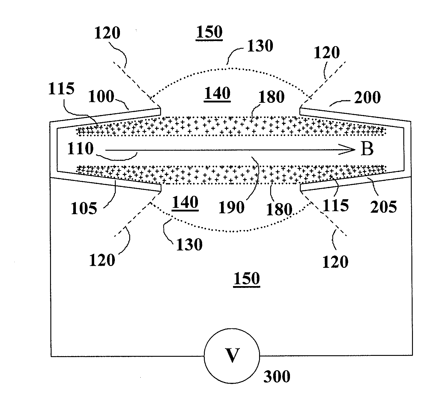
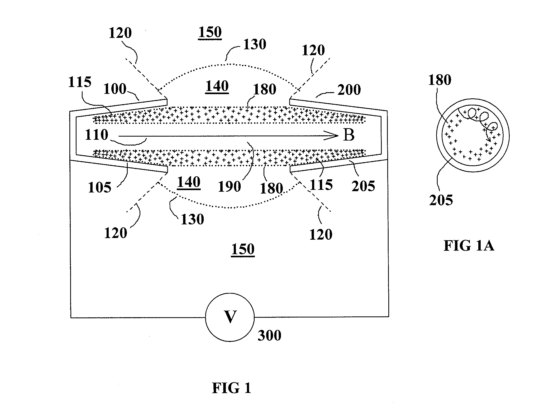
[0021]The operation of the invention is described with reference to FIG. 1, which shows a cross section of a two-electrode configuration with cylindrical symmetry about axis of rotation 110. Electrodes 100 and 200 are identical and opposed to each other. The outer envelope of each electrode, illustrated in cross section by broken lines 120 may be conical in shape. The interior of the electrode configuration within boundary 130 is filled with a low pressure working gas 140. When working gas 140 is a condensible metal vapor such as lithium, a buffer gas region 150 is used to contain and recycle the metal vapor according to the wide angle heat pipe principle (McGeoch, U.S. Pat. No. 7,479,646 (2009)). The heat pipe surfaces necessary for the reflux of liquid metal are not shown in FIG. 1, as they are not part of the present invention. A uniform magnetic field B is present parallel to the axis of symmetry 110 of the electrodes.

[0022]Alternating electric pulses are applied via voltage gen...

second embodiment

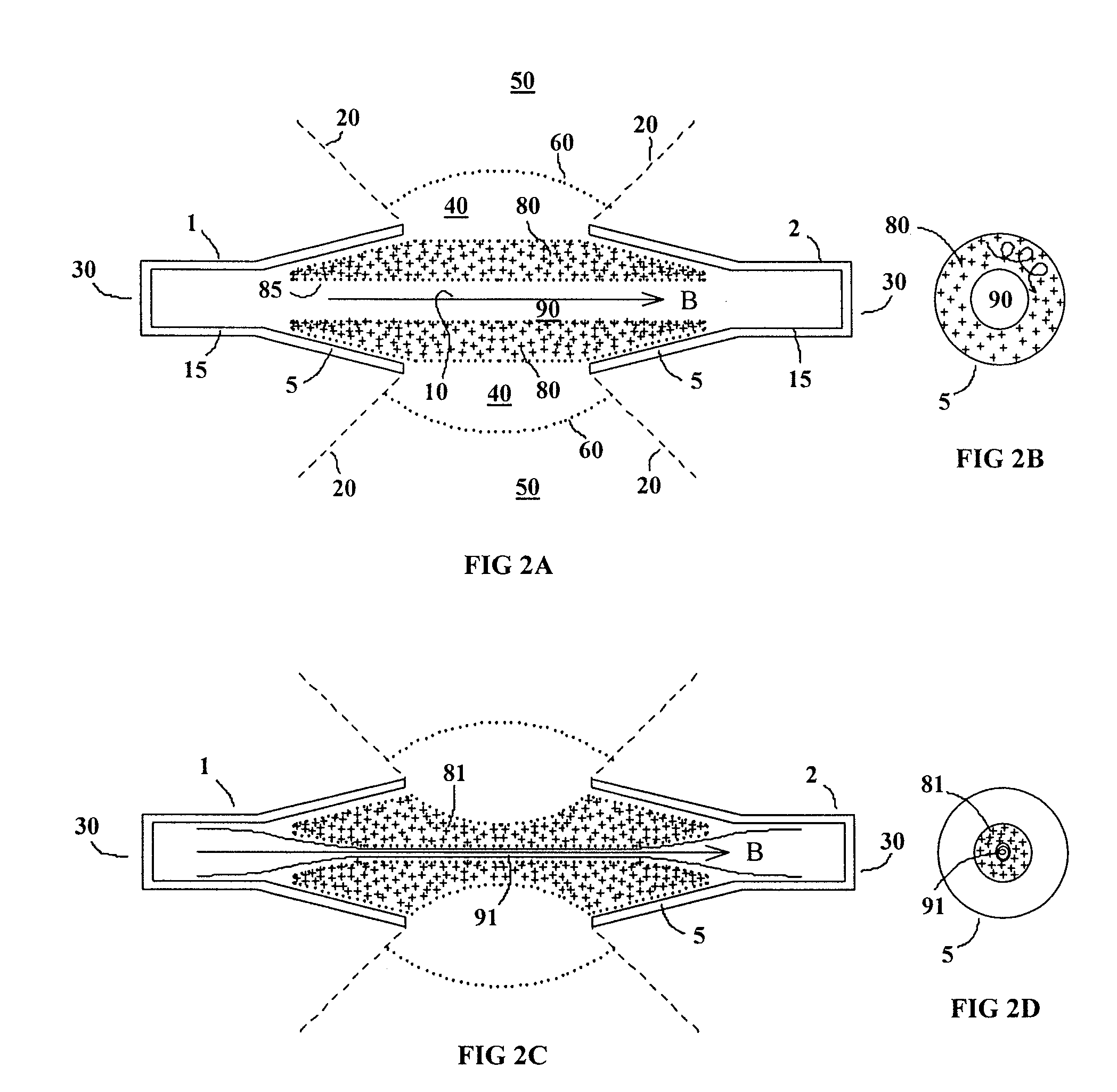
[0023]the invention that is able to generate a dense, cool, cylindrical plasma core is illustrated in FIGS. 2A-2D. Two identical opposed hollow electrodes 1, 2 have rotational symmetry about axis 10. The hollow interior of each electrode is composed of an outer flared portion 5, which may be conical, and an inner straight portion 15 which is cylindrical. The outer envelope of each electrode, illustrated in cross section by broken lines 20 in FIGS. 2A and 2C, may be conical in shape. The hollow electrodes 1, 2 have closures 30 at the outermost extent of cylindrical sections 15. A working gas 40, which may be lithium vapor, fills each hollow electrode and the region between them. If the working gas is a condensible metal such as lithium, there is a helium buffer region 50 surrounding it. The boundary 60 between the lithium working gas and the helium buffer is established by the disposition of a wide-angle heat pipe structure of the type described in U.S. Pat. No. 7,479,646 (McGeoch, 2...


PUM


Abstract

A configuration of two opposed electrodes with conical depressions and symmetry around an axis along which there is an applied steady magnetic field, is supplied with a pulsed voltage and current to create an azimuthally very uniform pre-ionization cylinder of a working gas as a precursor to stable and accurate compression of the working gas into a Z-pinch plasma photon source or plasma target for laser-pumped photon sources. A further compound hollow electrode configuration permits the generation of a cool, dense, core plasma surrounded and compressed by a hot liner plasma. Modulation of the radial density profile within this core can provide optical guiding for a laser-pumped recombination laser.

Description

RELATED APPLICATIONS[0001]This Application claims priority under 35 U.S.C. §119(e) to U.S. Provisional Application Ser. No. 61 / 253,239, entitled “GAS EMBEDDED Z-PINCH PLASMA GENERATOR AND PLASMA TARGET” filed on Oct. 20, 2009, which is incorporated herein by reference in its entirety.BACKGROUND OF INVENTION[0002]The Z-pinch, in which a cylindrical plasma column is compressed to high temperature by the self-magnetic field of a current passing axially along it, is of utility in the generation of ultraviolet, extreme ultraviolet or soft X-ray radiation. The history of the development of the Z-pinch is reviewed in an article entitled “The past, present and future of Z pinches” by M. G. Haines et al., Physics of Plasmas 7, pp 1672-1680 (2000). In contrast to the very high energy (MJ) pinch devices that are of relevance to nuclear fusion energy, the generation of 13.5 nm extreme ultraviolet (EUV) radiation for semiconductor lithography demands a high repetition rate source, ideally 10 kHz...

Claims


Application Information

Patent Timeline
IPC IPC(8): H05H1/24
CPCH05H1/06
Inventor MCGEOCH, MALCOLM W.
Owner PUREX
Why Eureka
Try Eureka