
Method for manufacturing a sensor component without passivation, and a sensor component

a manufacturing method and sensor technology, applied in the direction of fluid pressure measurement, acceleration measurement using interia forces, instruments, etc., can solve the problems of significant increase in manufacturing costs, and achieve the effect of minimizing manufacturing costs, cost-effectiveness, and simplifying the manufacturing process

Inactive Publication Date: 2011-04-21
ROBERT BOSCH GMBH
View PDF1 Cites 7 Cited by
  • Summary
  • Abstract
  • Description
  • Claims
  • Application Information

AI Technical Summary

Benefits of technology

[0014]The piezoresistive sensor layer preferably includes a carbon layer containing metal clusters, in particular metal clusters in amorphous carbon or metal clusters embedded into a graphite matrix. These structures permit the formation of a particularly hard and piezoresistive sensor layer which simultaneously also minimizes the influence of moisture on the measurement.
[0016]The piezoresistive sensor layer may be made solely of at least one metal and carbon / hydrocarbon and have between 30 and 70 at % metal, preferably between 45 and 55 at % metal, even more preferably between 50 and 55 at % metal. In particular, the metal is preferably nickel because the latter particularly effectively influences the properties of the sensor layer, such as the k factor and the temperature coefficient of resistance, offset and sensitivity as well as life cycle stability.
[0019]During wire bonding, the sensor layer may be contacted directly without any further contact layers. In the method according to the present invention, it is therefore possible to dispense with thin film passivation layers and contact layers, which significantly simplifies the manufacturing process and minimizes the manufacturing costs.

Problems solved by technology

However, such care results in a significant increase in manufacturing costs, due to the use of special tools as well as of fully automatic assembly and handling stations for the sensor elements.

Method used


Image

  • Method for manufacturing a sensor component without passivation, and a sensor component
  • Method for manufacturing a sensor component without passivation, and a sensor component
  • Method for manufacturing a sensor component without passivation, and a sensor component

Examples


Embodiment Construction

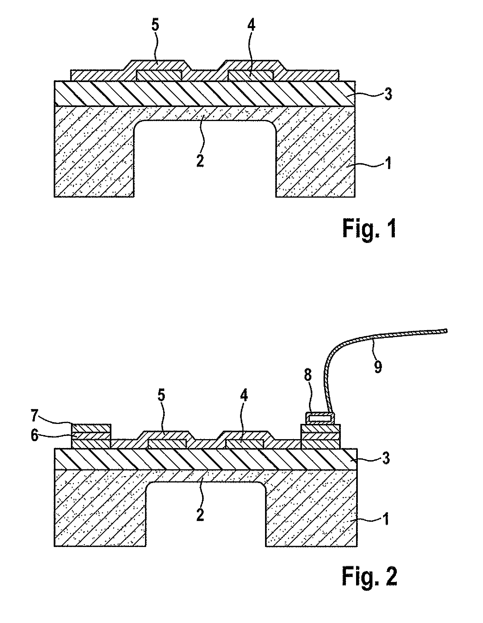
[0027]The present invention is described in detail below on the basis of the drawings. The exemplary embodiment refers to a thin film high-pressure sensor by way of example but is not limited thereto.

[0028]FIG. 1 shows a cross-sectional view of the schematic structure of a high-pressure sensor according to the related art, the high-pressure sensor being based on a metal diaphragm 2. However, a ceramic diaphragm 2 may also be used. The structure is formed as follows: Reference numerals 1 and 2 represent the deformation body, preferably a metal deformation body. This deformation body preferably has a monolithic structure. Reference numeral 1 represents a metal substrate, preferably a steel substrate, which includes a diaphragm 2 which seals a cavity in the deformation body. In FIG. 1, deformation body 1, 2 takes the form of a bridge, diaphragm 2 being the actual bridge section. In the case of a metal diaphragm 2, an electrical insulating layer 3, which prevents a conductive connection...


PUM


Abstract

A sensor component and a method for manufacturing a sensor component, in which a sealing passivation of a sensor layer may be dispensed with. For this purpose, the sensor component includes, in particular, a thin film high-pressure sensor, a deformation body and a piezoresistive sensor layer, which is applied to the deformation body, the piezoresistive sensor layer including at least one metal as well as carbon and / or hydrocarbon and terminating the layer structure of the sensor component. Based on the materials used a sealing cover of the sensor layer by a thin film passivation layer may be dispensed with. Additional contact layers for contacting the sensor layer may advantageously also be dispensed with. Contacting may then take place directly on the sensor layer, using a bond wire.

Description

FIELD OF THE INVENTION[0001]The present invention relates to a manufacturing method for a sensor component and to a sensor component, in particular a thin film high-pressure sensor which is terminated by the sensor layer and thus makes do without a passivation layer, preferably also without a contact layer on the sensor layer. In particular, the sensor component according to the present invention may be used in the automotive industry in vehicles.BACKGROUND INFORMATION[0002]In pressure sensors according to the related art, strain gauges are frequently used to measure deformation on the surface of components. Strain gauges are measuring devices for detecting expanding deformations. Even in the case of only slight deformations, they change their electrical resistance, which is used as a measure of deformation in a sensor. Strain gauges are based on a structured sensor layer or a functional layer which is applied to an insulating substrate or an insulator-coated, expandable substrate, ...

Claims


Application Information

Patent Timeline
Patent Type & Authority Applications(United States)
IPC IPC(8): H01L29/84H01L21/02
CPCG01L9/0042H01L2224/48091H01L2924/00014
Inventor SCHNEIDER, SIMONTRAUB, ANDREASJAHRSDOERFER, BERNDRUMPF, HOLGER
Owner ROBERT BOSCH GMBH
Learn More