
Fluid pressure actuator unit

Inactive Publication Date: 2011-04-21
KYB CORP
View PDF0 Cites 2 Cited by
  • Summary
  • Abstract
  • Description
  • Claims
  • Application Information

AI Technical Summary

Benefits of technology

[0004]The fluid pressure actuator unit that lifts the blade assembly of the lawn mower to the lifted position is required to operate in two operation modes, i.e. a loaded mode in which the fluid pressure cylinder is driven to lift the blade assembly and an unloaded mode in which the blade assembly is free to rise and fall by l

Problems solved by technology

The unloaded mode is therefore not available in the prior art fluid pressure actuator unit.

Method used


Image

  • Fluid pressure actuator unit
  • Fluid pressure actuator unit
  • Fluid pressure actuator unit

Examples


Embodiment Construction

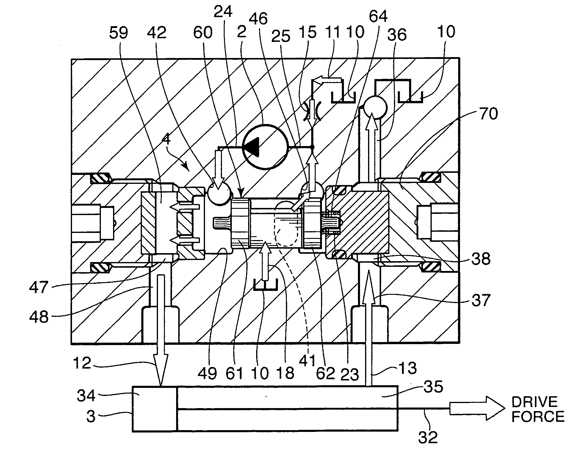
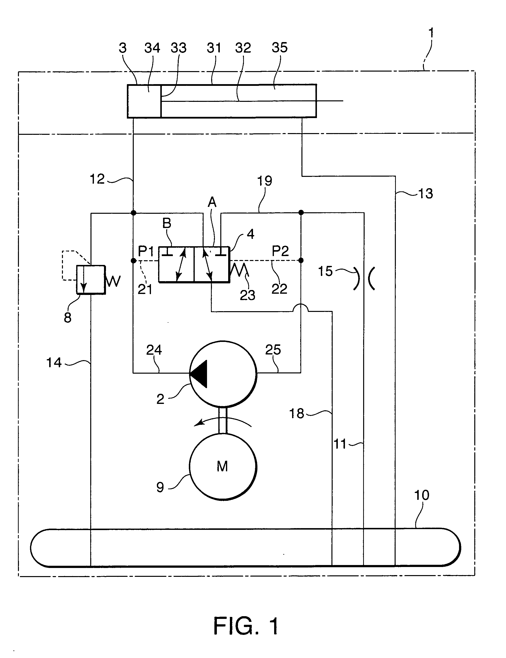
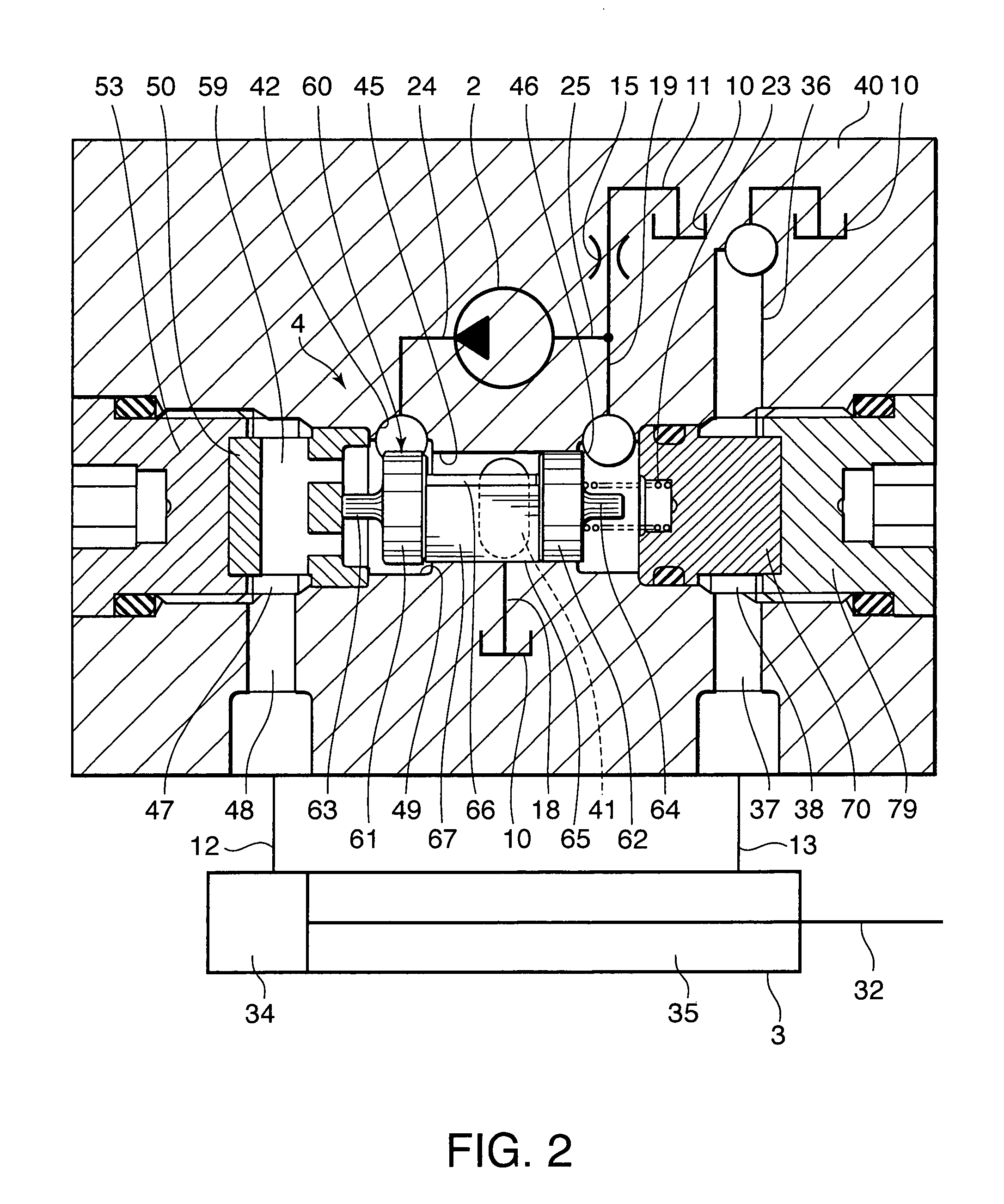
[0017]Referring to FIG. 1 of the drawings, a fluid pressure actuator unit 1 for a lawn mower according to this invention comprises a fluid pressure pump 2 driven by an electric motor 9, a fluid pressure cylinder 3 driven to elongate by a working fluid discharged by the fluid pressure pump 2, and a tank 10 that stores the working fluid.

[0018]The fluid pressure pump 2 comprises a discharge port 24 and a suction port 25. In response to an operation of the electric motor 9, the fluid pressure pump 2 aspirates working fluid from the suction port 25 and discharges the working fluid into the discharge port 24 in a pressurized state.

[0019]The fluid pressure cylinder 3 comprises a cylinder tube 31, a piston 33 accommodated in the cylinder tube 31 so as to be free to slide in an axial direction, and a piston rod 32 that is connected to the piston 33 and projects outside from the cylinder tube 31 in the axial direction. The cylinder tube 31 is filled with oil as the working fluid. The oil may ...


PUM


Abstract

A fluid pressure cylinder (3) is connected to a discharge port (24) of a fluid pressure pump (2). A suction port (25) of the fluid pressure pump (2) is connected to a tank (10) via a suction passage (11) in which a flow restrictor (15) is provided. A change-over valve (4) changes over operation modes of the fluid pressure cylinder (3) between a load mode in which the pressure cylinder (3) is driven by the fluid pressure pump (2) and an unload mode in which the fluid pressure cylinder (3) elongates and contracts according to an external force exerted thereon in response to a differential pressure between the discharge port and the suction port. Automatic change-over of the operation modes of the pressure cylinder (3) in response to an operation of the fluid pressure pump (2) is thereby realized.

Description

FIELD OF THE INVENTION[0001]This invention relates to a fluid pressure actuator unit used, for example, for supporting a blade assembly of a lawn mower in an operation position and lifting the blade assembly to a lifted position as required.BACKGROUND OF THE INVENTION[0002]A lawn mower comprises, for example, a vehicle body, a blade assembly, and an actuator. The blade assembly is supported by the mower vehicle body via a floating mechanism so as to be able to rise and fall in an operating position in response to an external force exerted thereon. The actuator lifts the blade assembly from the operating position to a lifted position and keeps it in the lifted position. The actuator may be provided in the form of a fluid pressure actuator unit into which an electric motor, a fluid pressure pump, and a fluid pressure cylinder are integrated.[0003]JP2006-105226A, published by the Japan Patent Office in 2006, proposes a fluid pressure actuator unit comprising an electric motor, a fluid ...

Claims


Application Information

Patent Timeline
IPC IPC(8): F15B15/18
CPCF15B11/08F15B13/0402F15B2211/20515F15B2211/7741F15B2211/41563F15B2211/50518F15B2211/7053F15B2211/40507
Inventor SATO, OSAMUNISHIOKA, SHIRO
Owner KYB CORP
Learn More